Grouting reinforcement and geotechnical reverse filtration test device and working method

A technology of grouting reinforcement and test device, which is applied to measurement devices, preparation of test samples, weighing by removing certain components, etc., can solve the problem that the pressure sensor is useless, the function of the test device is single, and the accuracy of key data is low. and other problems, to achieve the effect of improving segregation, flexible test scale, and improving mixing effect.

Pending Publication Date: 2021-05-28
SHANDONG JIANZHU UNIV +1
View PDF0 Cites 0 Cited by
  • Summary
  • Abstract
  • Description
  • Claims
  • Application Information

AI Technical Summary

Problems solved by technology

[0007] 1. The function of the test device is single, and it can only carry out a certain type of test or a single material test, and there are few reports on the test device for the performance test of the reverse filter material
[0008] 2. The adjustability of the

Method used


Image

  • Grouting reinforcement and geotechnical reverse filtration test device and working method
  • Grouting reinforcement and geotechnical reverse filtration test device and working method
  • Grouting reinforcement and geotechnical reverse filtration test device and working method

Examples


Example Embodiment

[0064]Example 2:

[0065]This example discloses the working method of the grouting reinforcement and geotextile test apparatus of Example 1, including the following steps:

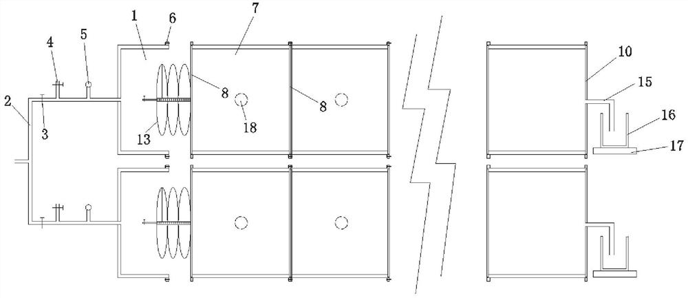
[0066]Step 1: Extunction the release agent in the inner wall of the first end test chamber, and secure the multi-hole plate in the mounting tank by the M2 screw, and wrap the outer surface of the porous plate with the PE film, and then inserted into the first end test chamber. It is compacted in accordance with the corresponding requirements of the Geotechnical Test Regulations. After the injection is filled, the multi-hole plate is fixed by the M2 screw, and the outer surface of the porous plate is wrapped with a PE film. Subsequently, weigh the first end test chamber quality M01. Finally, the coating group and the hollow tube jacket are in the fixed rod of the porous plate, and the pin is inserted into the fixed rod end.

[0067]Step 2: Extunction of the inner wall of the i-th test chamber, one end is fixed to the moun...

Example Embodiment

[0073]Example 3:

[0074]This example discloses the working method of the grouting reinforcement and geotextile test apparatus of Example 1, including the following steps:

[0075]Step A: Wipe the release agent evenly in the inner wall of the first end test chamber, one end is fixed in the mounting slot by the M2 screw, and wrap the outer surface of the porous plate with the PE film, and then fill the reflined filtration material to the first end test chamber. In this step, the diaphragm material uses clays and compacted according to the corresponding requirements of the "Geotechnical Test Regulations". After the filtration material is filled, the multi-hole plate is fixed to the other end of the first end test chamber with the M2 screw, and the outer surface of the porous plate is wrapped with a PE film. Subsequently, weigh the first end test chamber quality M21. Finally, the coating group and the hollow tube jacket are in the fixed rod of the porous plate, and the pin is inserted into t...


PUM


Abstract

The invention relates to a grouting reinforcement and geotechnical reverse filtration test device and a working method. The grouting reinforcement and geotechnical reverse filtration test device comprises an input cabin with one open end, the open end of the input cabin is connected with a test module assembly, and the test module assembly is formed by splicing a plurality of test boxes; The device comprises a head-end test box, a tail-end test box and a plurality of middle test boxes located between the head-end test box and the tail-end test box, perforated plates are arranged at the two ends of the test boxes, a stirring mechanism is arranged at the end, close to an input cabin, of the head-end test box, and the end, away from the input cabin, of the tail-end test box is sealed through a sealing plate which is connected with a recycling metering mechanism. The device provided by the invention can be used for carrying out various tests.

Description

Technical field[0001]The present invention relates to the technical field of test equipment, and more particularly to a grouting reinforcement and geotextile testing device and a working method.Background technique[0002]The statements herein provide only the background techniques associated with the present invention, and it is not necessary to form a prior art.[0003]With the in-depth development of infrastructure, tunnel engineering, water conservancy projects, foundation pit projects are more increasing, and geological conditions are also more complex. For example, the weak sandstone layer has been loose and broken due to its structure, and the rich water is strong. It has become a unveiled geological problem of the situation. It has seriously affected the construction and operation of the tunnel engineering; the reasonable reflined layer in the water conservancy project is required. The antity filtration must have a sufficiently small pore to prevent the soil particles from being...

Claims


Application Information

Patent Timeline
IPC IPC(8): G01N15/08G01N5/02G01N5/04G01N1/28G01N1/36G01N1/38
CPCG01N1/28G01N1/36G01N1/38G01N5/02G01N5/04G01N15/0806G01N15/0826G01N2001/366
Inventor 冯啸李传贵赵宏魁武剑峰夏冲胡文军张思峰李献刚孔祥辉殷敬敬
Owner SHANDONG JIANZHU UNIV
Why Eureka
Try Eureka