Demonstration method of power distribution network dispatching system

A technology of scheduling system and demonstration method, applied in special data processing applications, instruments, other database retrieval and other directions, can solve the problems of energy and time, high cost, increase labor cost, etc., and achieve the effect of cost saving

Inactive Publication Date: 2021-05-28
北京中兆龙芯软件科技有限公司
View PDF0 Cites 0 Cited by
  • Summary
  • Abstract
  • Description
  • Claims
  • Application Information

AI Technical Summary

Problems solved by technology

[0003] However, in the existing dispatching and monitoring system, once there is a little error, the method of manual point-to-point is generally adopted, combined with point-to-point table point-to-point, which is very labor-intensive and time-consuming; labor costs increase
[0004] Furthermore, when the power supply company needs to add user nodes (this must be reasonable), then the original screen editing wiring diagram must be changed to a certain extent, the scheduling software graphics must be changed to a certain extent, the point table must be re-aligned, and the data must also be adjusted accordingly. change; the report curve must also change; the degree of freedom is extremely poor; it will increase labor costs
[0005] Finally, if there are hundreds or even thousands of projects, each project has almost different wiring diagram differences, and each project needs to be edited once; the labor cost is higher, although the project is more perfect, the cost increases Too high does not meet current needs

Method used


Image

  • Demonstration method of power distribution network dispatching system
  • Demonstration method of power distribution network dispatching system
  • Demonstration method of power distribution network dispatching system

Examples


Embodiment Construction

[0068] The following will clearly and completely describe the technical solutions in the embodiments of the present invention with reference to the accompanying drawings in the embodiments of the present invention. Obviously, the described embodiments are only some, not all, embodiments of the present invention. Based on the embodiments of the present invention, all other embodiments obtained by persons of ordinary skill in the art without making creative efforts belong to the protection scope of the present invention.

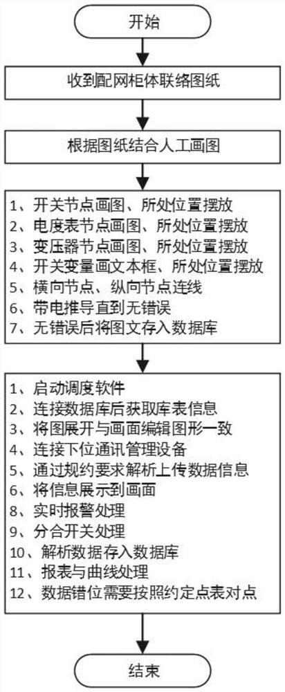
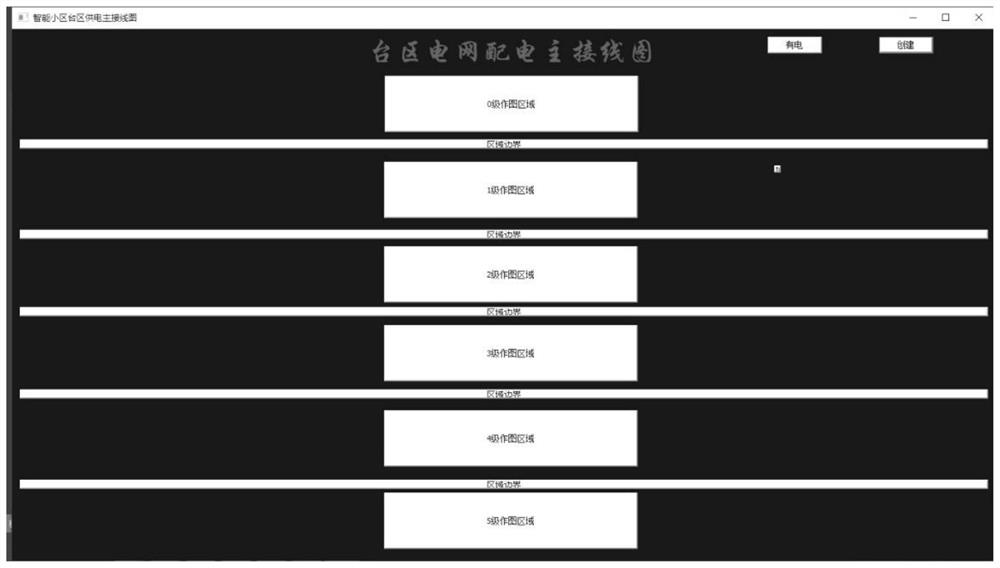
[0069] Such as Figure 1-13 As shown, an embodiment of the present invention provides: a demonstration method of a power distribution network dispatching system, comprising the following steps:

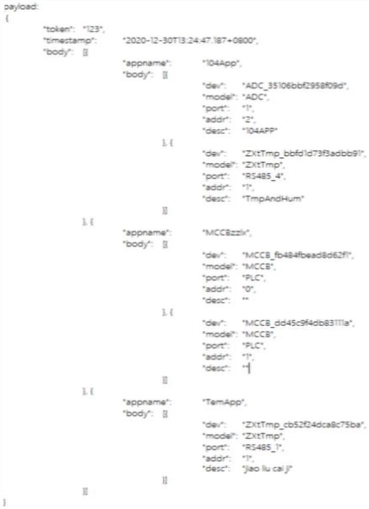
[0070] Step 1: The address of each switch, transformer, and watt-hour meter under each station area managed by each power supply company includes the station area number and the unique number of the equipment in the station area; this ensures that each station area T...


PUM


Abstract

The invention discloses a demonstration method of a power distribution network dispatching system, which adopts a communication data character string format to automatically generate a topological structure diagram, and does not need to edit a picture to process a graphical interface in a project implementation process; point alignment in the implementation process is not needed; when a power supply company needs to increase or reduce transformer area users, only hardware switches and matched connecting lines are added, graphs are automatically generated in the information transmission process, the users are increased or reduced, only simple configuration is needed, and point alignment and drawing are not needed; in the implementation process of a plurality of projects, topological structure diagrams are automatically generated, the problem that graphs and real wiring are different does not need to be concerned, and overall implementation is divided into two parts; the first part is to receive the number of all devices in a transformer area and relational data among the devices; the second part is to carry out drawing according to the relation data; and the method is visual and clear, accords with software architecture design standards, and saves cost.

Description

technical field [0001] The invention relates to the technical field of electric power distribution network dispatching system, in particular to a demonstration method of electric power distribution network dispatching system. Background technique [0002] In recent years, the power distribution network dispatching system has been widely applied to various power supply companies, which greatly improves the management efficiency and automation level. Generally speaking, the distribution network dispatching system is composed of the following parts: communication connection, screen editing processing on the software based on the known distribution network cabinet contact diagram, and a database is generated after the screen editing processing, and the database table contains the switch The horizontal connection and vertical connection information of the node, the software establishes the database connection, reads the database table, generates the distribution network wiring di...

Claims


Application Information

Patent Timeline
IPC IPC(8): G06F16/904G06Q10/06G06Q50/06
CPCG06Q10/0631G06Q50/06G06F16/904
Inventor 付和平郭小广黄钲钧景红孙立新孙小程
Owner 北京中兆龙芯软件科技有限公司
Why Eureka
Try Eureka