Punching-resistant concrete-filled steel tube column foot structure and punching-resistant capacity estimation method thereof

A steel tube concrete column, anti-punching technology, applied in the direction of foundation structure engineering, columns, pier columns, etc., can solve the problems of thick protruding rafts, complex waterproof construction of formwork, etc., to improve the anti-punching ability, reduce The effect of concrete dosage and thickness reduction

Pending Publication Date: 2021-05-28
CHINA NORTHWEST ARCHITECTURE DESIGN & RES INST CO LTD
View PDF0 Cites 1 Cited by
  • Summary
  • Abstract
  • Description
  • Claims
  • Application Information

AI Technical Summary

Problems solved by technology

In the existing design of concrete-filled steel tube column feet, the design is usually carried out according to the actual project according to the specification requirements. When the embedded column foot is used, due to the reason of punching resistance, the thickness of the raft at the column part is relatively thick, and generally protrudes The thickness of the raft is relatively large, and the formwork and waterproof construction are complicated

Method used


Image

  • Punching-resistant concrete-filled steel tube column foot structure and punching-resistant capacity estimation method thereof
  • Punching-resistant concrete-filled steel tube column foot structure and punching-resistant capacity estimation method thereof
  • Punching-resistant concrete-filled steel tube column foot structure and punching-resistant capacity estimation method thereof

Examples


Embodiment 1

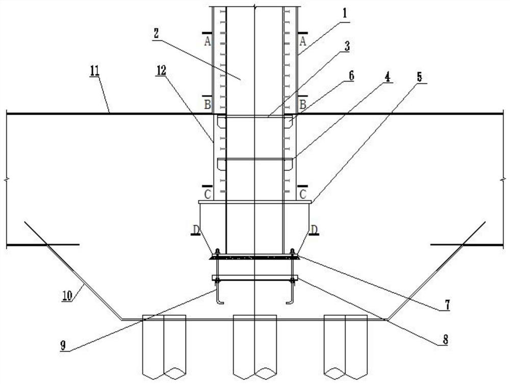
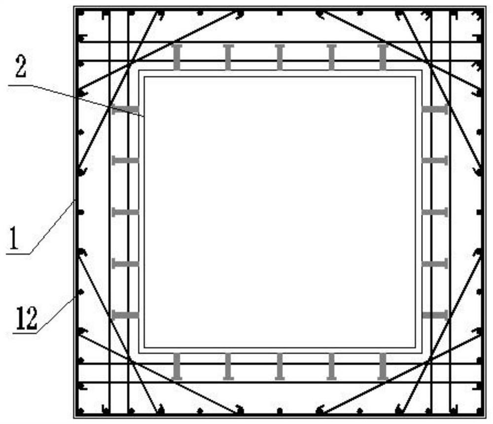
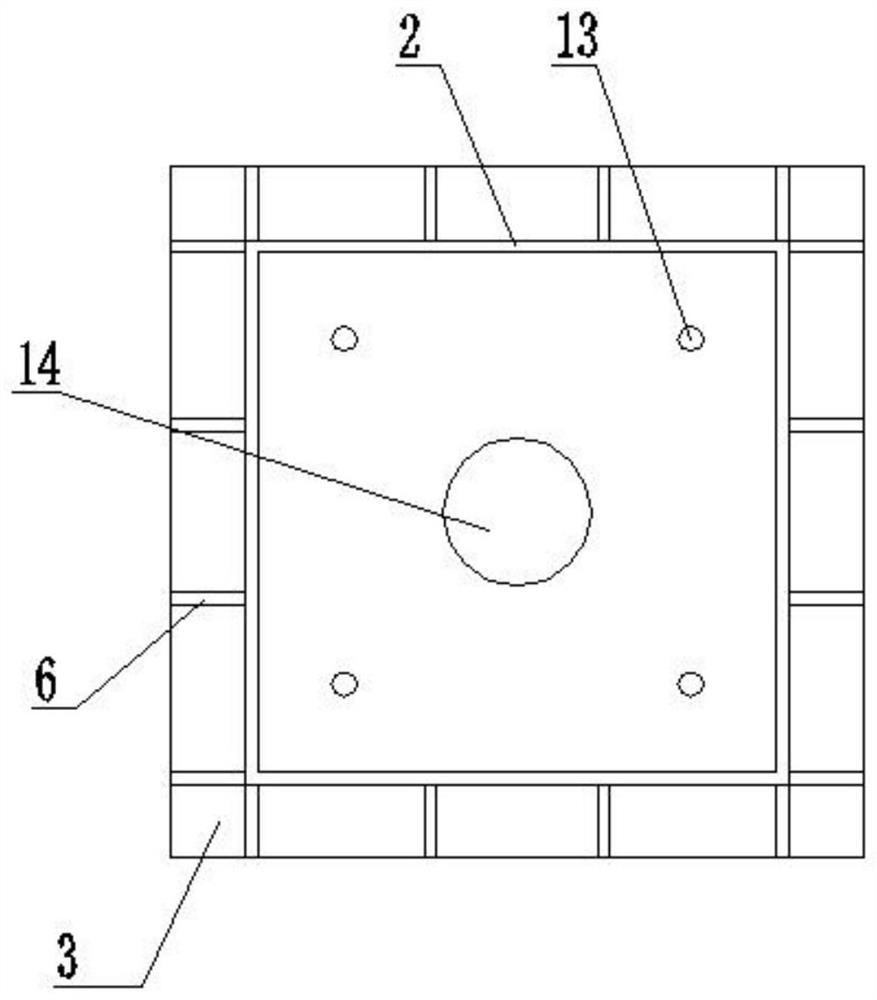
[0077] The punching-resistant concrete-filled steel tube column base structure in the super high-rise building of this embodiment includes the first punching-resistant ring plate 3, the second punching-resistant ring plate 4 and the third anti-punching ring plate arranged along the steel tube concrete column 1 from top to bottom. Punching ring plate 5, wherein the radial width of the first punching-resistant ring plate 3 and the second punching-resistant ring plate 4 is smaller than the radial width of the third punching-resistant ring plate 5; the first punching-resistant ring plate 3 and the second anti-punching ring plate 4, the distance L2 between the second anti-punching ring plate 4 and the third anti-punching ring plate 5, and the distance between the third anti-punching ring plate 5 and the bottom of the column foot The distance L3 between the plates 7 and the distance L4 between the bottom plate 7 of the column foot and the bottom of the concrete foundation 10 satisfy:...

Embodiment 2

[0095] In this example, the axial tensile force N b It is 14000kN, the cross-sectional size of the steel pipe 2 columns is 1100mm*1100mm*30mm, the strength grade of the outsourcing and inner pouring concrete are both C60, the concrete outsourcing size is 250mm, the longitudinal reinforcement is 48C32, the first punching shear ring plate 3, the second anti The lengths of the punching ring plate 4 , the third punching-resistant ring plate 5 and the column base plate 7 are 150mm, 150mm, 500mm and 250mm respectively.

[0096]When the steel tube concrete column 1 bears the tensile force, multiple stacked anti-punching shear surfaces are formed on the multiple punching-shearing ring plates and the column base plate 7; The punching resistance is calculated by the following formula:

[0097] A s =1100 2 -1040 2 =128400mm 2

[0098] A s1 =48×804=38592mm 2

[0099]

[0100] A 2 =1400 2 -1100 2 =750000mm 2

[0101] A 3 =2100 2 -1100 2 =3200000mm 2

[0102] A 4 =160...


PUM


Abstract

The invention belongs to the technical field of building structure engineering, and particularly relates to an anti-punching concrete-filled steel tube column foot structure and an anti-punching capability estimation method thereof. The punching-resistant concrete filled steel tubular column is characterized by further comprising a plurality of punching-resistant annular plates welded to the outer side of the concrete filled steel tubular column and stiffening plates connected to the bottoms of the punching-resistant annular plates, and anchor bolt supports are arranged in the middles of the column foot anchor bolts; the upper surface of the punching-resistant annular plate located on the uppermost layer is tightly attached to the lower edge of a surface rib of the concrete foundation, and the surface rib of the concrete foundation is welded to the punching-resistant annular plate on the uppermost layer. The lower ends of the longitudinal steel bars of the concrete filled steel tubular column extend to the anti-punching annular plate located in the middle and are bent and welded to the anti-punching annular plate. And by adding a plurality of anti-punching surfaces, the anti-punching bearing capacity of the foundation is increased, and uniform transmission of stress of the whole column foot is ensured.

Description

technical field [0001] The invention belongs to the technical field of building structure engineering, and in particular relates to a punching-shearing-resistant steel pipe concrete column base structure and a method for estimating the punching-shearing resistance thereof. Background technique [0002] Because of its high strength, good ductility, fatigue resistance, and impact resistance, concrete filled steel tubes are widely used in architectural structural engineering, especially in high-rise buildings. In the existing design of concrete-filled steel tube column feet, the design is usually carried out according to the actual project according to the specification requirements. When the embedded column foot is used, due to the reason of punching resistance, the thickness of the raft at the column part is relatively thick, and generally protrudes The thickness of the raft is relatively large, and the formwork and waterproof construction are complicated. Contents of the i...

Claims


Application Information

Patent Timeline
Patent Type & Authority Applications(China)
IPC IPC(8): G06F30/13G06F30/17G06F30/20E04C3/34E02D27/42G06F119/14
CPCE02D27/42E04C3/34G06F30/13G06F30/17G06F30/20G06F2119/14
Inventor 刘锋吴琨李丹莎王世斌潘映兵陶倍林龙婷
Owner CHINA NORTHWEST ARCHITECTURE DESIGN & RES INST CO LTD
Why Eureka
Try Eureka