
Clock constraint file collection method, device, equipment and storage medium

A technology for constraining files and obtaining methods, which is applied in the field of obtaining clock constrained files, can solve problems such as low development efficiency, failure to use normally, manual writing errors, etc., to improve accuracy and reliability, improve development efficiency, and save writing the effect of time

Pending Publication Date: 2021-05-28
SANECHIPS TECH CO LTD
View PDF0 Cites 0 Cited by
  • Summary
  • Abstract
  • Description
  • Claims
  • Application Information

AI Technical Summary

Problems solved by technology

[0003] As one of the core businesses of chip R&D, the development of clock constraint files plays an extremely important role in chip R&D. Traditional clock constraint files rely on manual writing, which takes a lot of time to write, and the development efficiency is extremely low, making the chip data delivery The time is too long, which increases the development cycle of the chip. At the same time, the manual writing method is prone to writing errors, which leads to chaotic timing and cannot be used normally.

Method used


Image

  • Clock constraint file collection method, device, equipment and storage medium
  • Clock constraint file collection method, device, equipment and storage medium
  • Clock constraint file collection method, device, equipment and storage medium

Examples


Embodiment 1

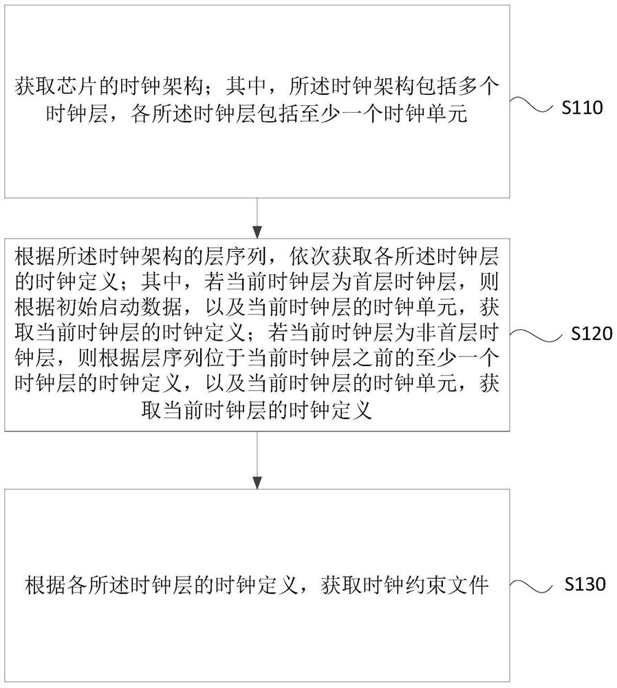
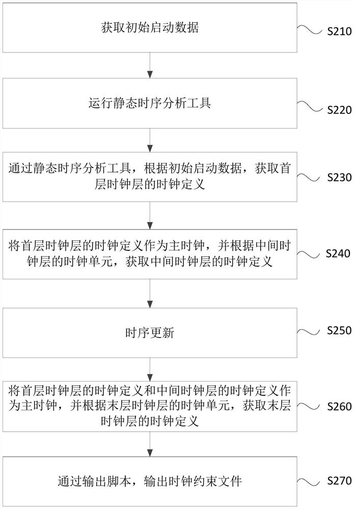
[0027] Figure 1A It is a flowchart of a method for obtaining a clock constraint file provided in Embodiment 1 of the present application. This embodiment is applicable to generating a clock constraint file of a chip, and the method can be executed by the device for obtaining a clock constraint file in the embodiment of the present application. , the device can be realized by software and / or hardware, and can generally be integrated in a chip, and the method specifically includes the following steps:

[0028] S110. Acquire a clock architecture of the chip; wherein, the clock architecture includes multiple clock layers, and each clock layer includes at least one clock unit.

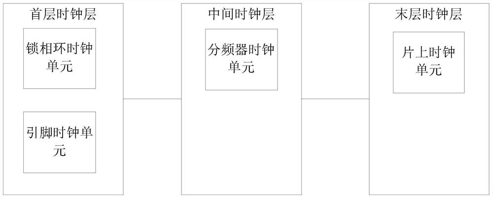
[0029] The clock is a periodic pulse signal, which is used to provide a time reference for data transmission between synchronously executed circuits in the chip, and to ensure the synchronous operation of each component unit in the chip. According to different functional requirements of the chip, the trans...

Embodiment 2

[0059] figure 2 It is a structural block diagram of a clock constraint file acquisition device provided in Embodiment 2 of the present application, and the device specifically includes: a clock architecture acquisition module 210 , a clock definition acquisition module 220 and a constraint file acquisition module 230 .

[0060] A clock architecture acquisition module 210, configured to acquire the clock architecture of the chip; wherein, the clock architecture includes multiple clock layers, and each clock layer includes at least one clock unit;

[0061] The clock definition acquisition module 220 is used to sequentially acquire the clock definition of each clock layer according to the layer sequence of the clock architecture; wherein, if the current clock layer is the first clock layer, then according to the initial startup data and the current clock layer Clock unit, to obtain the clock definition of the current clock layer; if the current clock layer is a non-first clock l...

Embodiment 3

[0079] image 3 It is a schematic structural diagram of a device provided in Embodiment 3 of the present application. image 3 A block diagram of an exemplary device 12 suitable for implementing embodiments of the present application is shown. image 3 The device 12 shown is only an example, and should not impose any limitation on the functions and scope of use of the embodiments of the present application.

[0080] Such as image 3 As shown, device 12 takes the form of a general purpose computing device. Components of device 12 may include, but are not limited to: one or more processors or processing units 16, system memory 28, bus 18 connecting various system components including system memory 28 and processing unit 16.

[0081] Bus 18 represents one or more of several types of bus structures, including a memory bus or memory controller, a peripheral bus, an accelerated graphics port, a processor, or a local bus using any of a variety of bus structures. These architectur...


PUM


Abstract

The embodiment of the invention discloses a clock constraint file collection method, a device, equipment and a storage medium. The method comprises the steps of obtaining a clock architecture of a chip, wherein the clock architecture comprises a plurality of clock layers, and each clock layer comprises at least one clock unit; according to the layer sequence of the clock architecture, obtaining clock definitions of all the clock layers in sequence; and obtaining a clock constraint file according to the clock definition of each clock layer. According to the technical scheme provided by the embodiment of the invention, the clock definitions of all the clock layers of which the layer sequence is located before the current clock layer are taken as the main clock of the current clock layer, and the clock definitions of all the clock layers are sequentially collected, so that the clock constraint file is collected according to the clock definitions of all the clock layers, automatic generation of the clock constraint file is realized, and the generation efficiency is improved. The writing time is saved, the development efficiency is improved, the research and development cycle of the chip is shortened. Meanwhile, the accuracy and reliability of writing the clock constraint file are improved.

Description

technical field [0001] The embodiments of the present application relate to chip technology, and in particular to a method, device, device and storage medium for acquiring a clock constraint file. Background technique [0002] With the continuous advancement of science and technology, chip technology has developed rapidly. While the size of the chip has been continuously reduced, its functionality has become stronger and stronger. The complexity of chip design has also increased exponentially. This affects the efficiency of chip research and development, especially for large-scale The efficiency of chip research and development puts forward higher requirements. [0003] As one of the core businesses of chip R&D, the development of clock constraint files plays an extremely important role in chip R&D. Traditional clock constraint files rely on manual writing, which takes a lot of time to write, and the development efficiency is extremely low, making the chip data delivery If ...

Claims


Application Information

Patent Timeline
Patent Type & Authority Applications(China)
IPC IPC(8): G06F30/30
Inventor 黄新星徐华锋
Owner SANECHIPS TECH CO LTD
Learn More