
High-voltage distribution network reactive power planning method for preventing capacitive reactive power reverse transmission

A high-voltage power distribution, capacitive reactive power technology, applied in the direction of reactive power adjustment/elimination/compensation, reactive power compensation, circuit devices, etc., can solve the problems of insufficient voltage regulation capacity of the upper substation, power grid security and stability, etc.

Pending Publication Date: 2021-05-28
DONGHUA UNIV
View PDF0 Cites 0 Cited by
  • Summary
  • Abstract
  • Description
  • Claims
  • Application Information

AI Technical Summary

Problems solved by technology

[0005] The purpose of the present invention is to overcome the defects of the prior art, provide a reactive power planning method for high-voltage distribution network that prevents capacitive reactive power transfer, establish a reactive power planning model, and adopt an improved genetic algorithm based on power factor reactive power sensitivity Solve the optimal reactive power planning model of the system, obtain the optimal configuration scheme of capacitors and reactors, and solve the problem caused by capacitive reactive power reversed to the upper power grid under the development situation of high-voltage distribution network cableization and increasing peak-valley difference Insufficient voltage regulation capacity of superior substation and safety and stability of power grid

Method used


Image

  • High-voltage distribution network reactive power planning method for preventing capacitive reactive power reverse transmission
  • High-voltage distribution network reactive power planning method for preventing capacitive reactive power reverse transmission
  • High-voltage distribution network reactive power planning method for preventing capacitive reactive power reverse transmission

Examples


Embodiment Construction

[0036] In order to enable those skilled in the art to better understand the technical solution of the present invention, its specific implementation is described in detail below:

[0037] In an embodiment of the present invention, a method for reactive power planning of a high-voltage distribution network that prevents capacitive reactive power transfer includes the following steps:

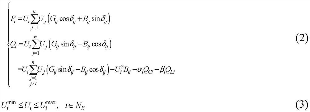
[0038]S1, establish a reactive power planning model for high-voltage distribution network considering power factor constraints, including:

[0039] S11. Determine the objective function of the reactive power planning of the high-voltage distribution network: the reactive power planning objective function minf of the high-voltage distribution network consists of three parts, which are respectively the reactive power investment cost of the capacitor, the reactive power investment cost of the reactor and the active network of the distribution network Electricity loss fee, as shown in formula (1),

...


PUM


Abstract

The invention discloses a high-voltage power distribution network reactive power planning method for preventing capacitive reactive power reverse transmission. According to the method, a comprehensive reactive power planning model which comprises a reactor and a capacitor and considers power factor constraints is built; according to the model, the simultaneous configuration of the capacitor and the reactor in a high-voltage power distribution system is considered, a minimum sum of reactive compensation equipment investment and active power loss cost in a planning period is taken as an objective function, node power factor constraints are added in the constraints; an improved genetic algorithm based on power factor reactive sensitivity is proposed; and the proposed model is solved, so thata capacitor and reactor reactive planning scheme is obtained; time-sharing switching is carried out in peak and valley periods, the power factor constraints can be met, capacitive reactive power is prevented from being reversely transmitted to a superior power grid; and the problems of reactive power reverse transmission and power factor out-of-limit occur when the high-voltage power distribution network with the peak and valley difference increasing day by day is in low load are solved.

Description

technical field [0001] The invention relates to a reactive power planning method for a high-voltage distribution network that prevents capacitive reactive power transfer. Background technique [0002] At present, the line parameters and load characteristics of large-scale urban high-voltage distribution networks are showing new changes. In terms of load characteristics, the peak-to-valley difference of power grid load is showing an increasing trend; in terms of line parameters, since the original high-voltage overhead distribution network is gradually transformed into a cable network, the capacitive reactive charging power of the line is far beyond the past. In large cities represented by Shanghai, the daily maximum peak-to-valley difference rate has exceeded 40%, and the cable conversion rate of 110kV lines has exceeded 60%. Under the new development trend, the problem of excess capacitive reactive power under the low-valley load operation state is becoming more and more p...

Claims


Application Information

Patent Timeline
IPC IPC(8): H02J3/18
CPCH02J3/18H02J2203/20Y02E40/30
Inventor 邢洁曹瑞琳景小敏郭斌刘洋孙嘉曈马洪艳
Owner DONGHUA UNIV
Learn More