
IGBT press-fitting structure
A press-fit structure and pressure-receiving plate technology, which is applied in the direction of transforming equipment structural parts, emergency protection circuit devices, output power conversion devices, etc., can solve the problems of poor operation stability of DC fault ride-through capability, achieve compact structure, improve The effect of stable operation and improved stability
- Summary
- Abstract
- Description
- Claims
- Application Information
AI Technical Summary
Problems solved by technology
Method used
Image

Examples
Embodiment Construction
[0058]The present invention will be further described in detail below with reference to the accompanying drawings.
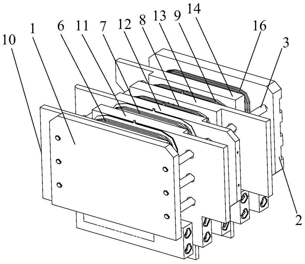
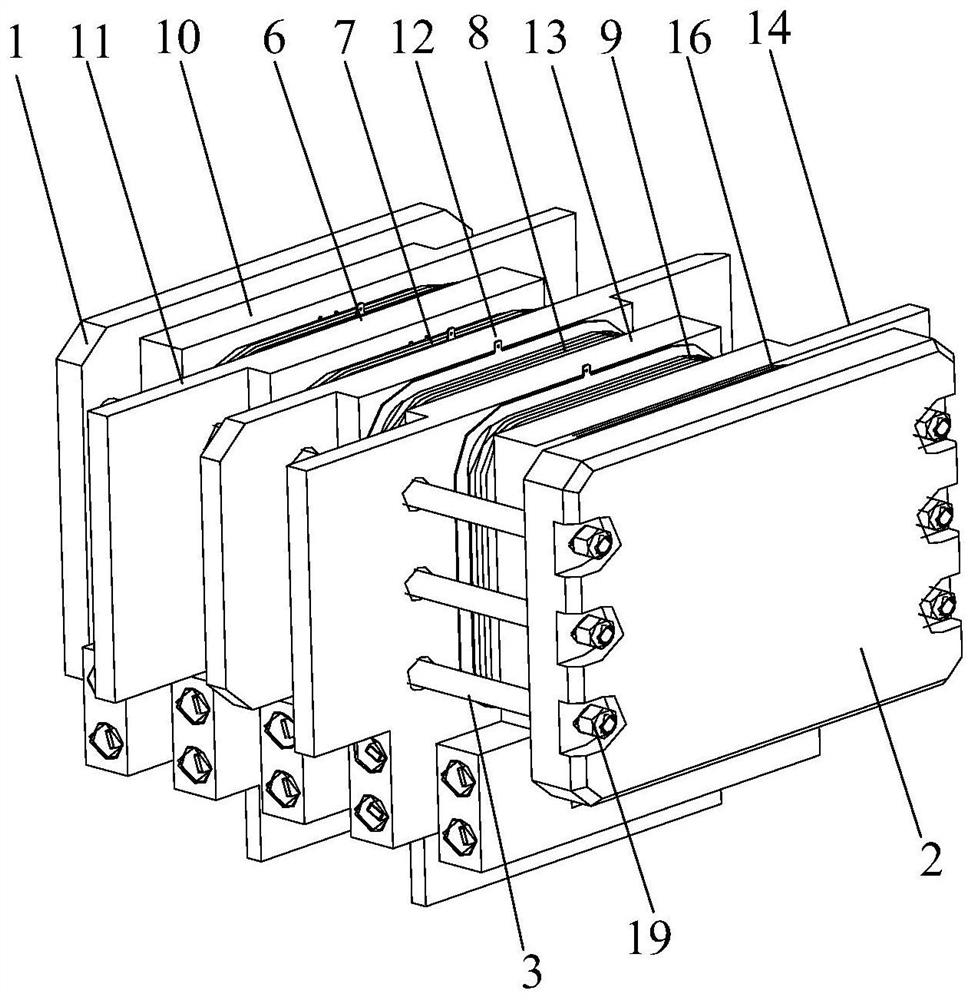
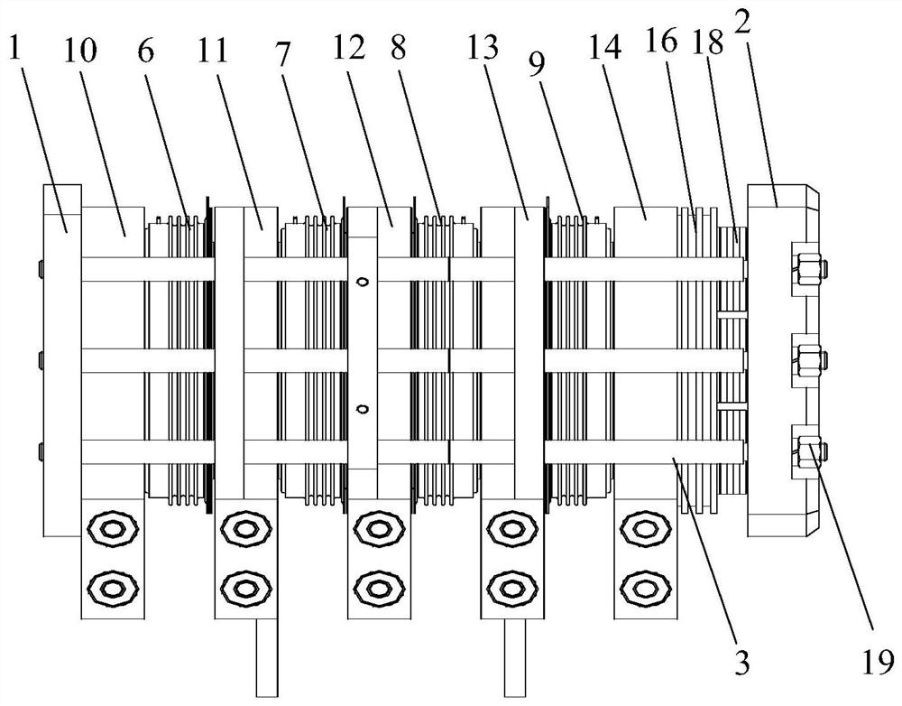
[0059]Embodiments of the present invention provide an IGBT press structure, including IGBT components, radiator components, and support components;Figure 1 - Figure 4As shown, the support assembly includes a first end plate 1, a second end plate 2, and a tie rod assembly; the first end plate 1 and the second end plate 2 are arranged in parallel, and both ends of the tie rod assembly are respectively connected to the first end plate 1 and the second. The end plate 2 is fixed, that is, one end of the tie rod assembly is fixed to the first end plate 1 by the thread, and the other end of the tie rod assembly passes through the through hole of the second end plate 2, and then the nut 19 is fastened. The first end plate 1, the second end plate 2, and the tie rod assembly form a housing space; the IGBT assembly and the heat sink assembly are disposed inside the accommodating sp...
PUM
 Abstract
Description
Claims
Application Information