Steel bar specified-length cutting equipment for house building

A technology for specifying the length and cutting equipment, applied in the direction of mechanical equipment, engineering safety devices, etc., can solve the problems of non-adjustable effective length of steel bars, inability to carry out automatic transportation, inability to adapt to flexible use of construction projects, etc., to prevent splashing around and facilitate Collection, good effect of cutting work

Active Publication Date: 2021-06-01
江西清江建设发展有限公司
View PDF7 Cites 4 Cited by
  • Summary
  • Abstract
  • Description
  • Claims
  • Application Information

AI Technical Summary

Problems solved by technology

[0005] In order to overcome the shortcomings of being unable to carry out automatic transportation, being unable to adapt to the flexible use of construction projects, and not being able to adjust the effective length of steel bars, the technical problem to be solved is: to provide a method that can automatically cut steel bars, and can lengthen the cut steel bars. Conditioned steel bar cut-to-length equipment for building construction

Method used


Image

  • Steel bar specified-length cutting equipment for house building
  • Steel bar specified-length cutting equipment for house building
  • Steel bar specified-length cutting equipment for house building

Examples


Embodiment 1

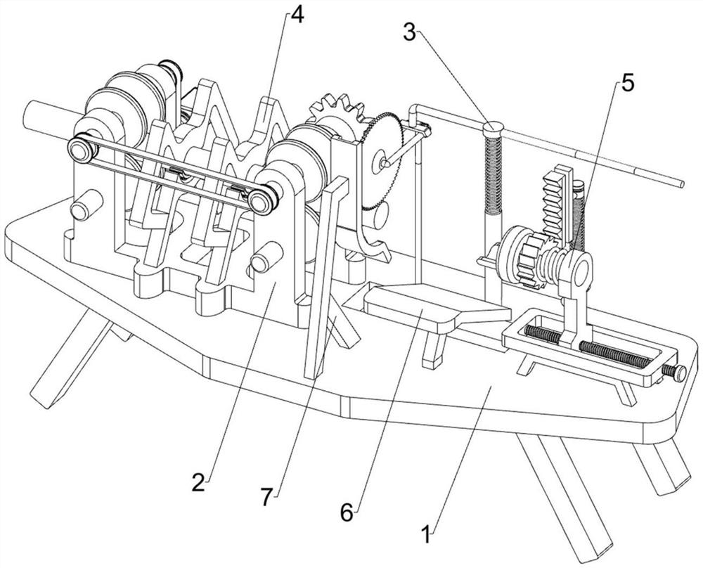
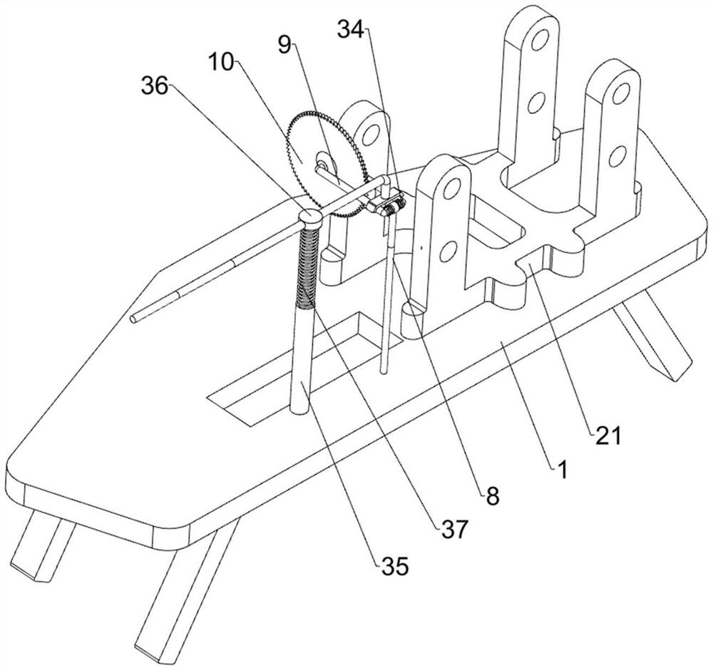
[0062] A device for cutting steel bars to a specified length for building construction, such as figure 1 with image 3 As shown, it includes a base 1, a transmission mechanism 2, a pressing mechanism 3, a mounting column 8, a mounting rod 9 and an electric cutting wheel 10, a pressing mechanism 3 is provided in the middle of the top of the base 1, and a transmission mechanism is provided on the left side of the top of the base 1 2. A mounting column 8 is provided on the rear side of the top of the base 1, a mounting rod 9 is installed on the mounting column 8 in a rotating manner, and an electric cutting wheel 10 is provided on the front side of the mounting rod 9.

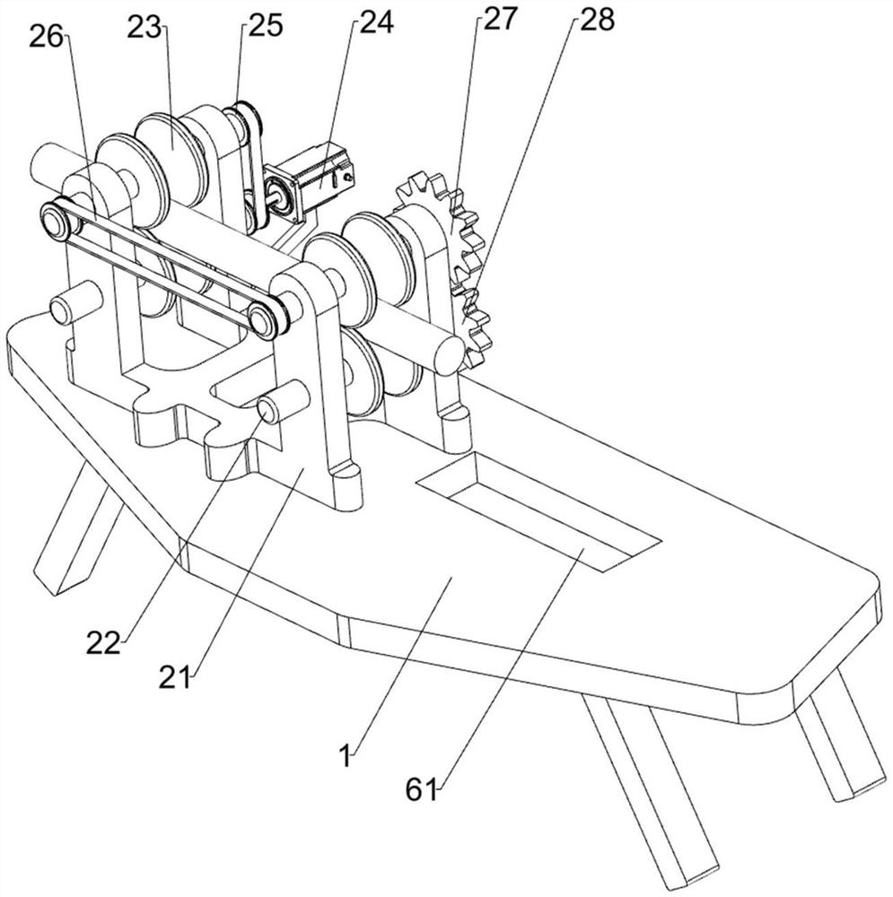
[0063] Such as figure 2 As shown, the transmission mechanism 2 includes a mounting frame 21, a first transmission wheel 22, a second transmission wheel 23, a servo motor 24, a first belt 25, a second belt 26, a first full gear 27 and a second full gear 28, Base 1 top left side is provided with mounting frame 21...

Embodiment 2

[0067] On the basis of Example 1, such as Figure 4 with Figure 5 As shown, a buffer mechanism 4 is also included, and the buffer mechanism 4 includes a buffer frame 41, a buffer plate 42, an upper top plate 43, a lower top plate 44, an adjustment plate 45 and a third spring 46, and the left and right sides of the top of the mounting frame 21 are all symmetrical A buffer frame 41 is provided, and a buffer plate 42 is provided on the outside of the buffer frame 41. An upper top plate 43 is connected between the buffer plates 42 on the left and right sides, and a lower top plate 44 is connected between the buffer frames 41 on the left and right sides. 44 is provided with an adjustment plate 45 slidingly, and a third spring 46 is connected between the adjustment plate 45 and the lower top plate 44 .

[0068] In the process of the steel bar moving to the right, the steel bar will be between the upper top plate 43 and the adjustment plate 45, so that the adjustment plate 45 moves...


PUM


Abstract

The invention relates to cutting equipment, in particular to steel bar specified-length cutting equipment for a house building. The technical problem to be solved is to provide the steel bar specified-length cutting equipment for the house building. The steel bar specified-length cutting equipment for the house building can automatically cut steel bars and can adjust the length of the cut steel bars. According to the technical scheme, the steel bar specified-length cutting equipment for the house building comprises a base, a conveying mechanism, a mounting column and a mounting rod. A downward pressing mechanism is arranged in the middle of the top of the base. The conveying mechanism is arranged on one side of the top of the base. The mounting column is arranged on one side of the top of the base. The mounting rod is rotationally arranged on the mounting column. The steel bars can be automatically moved through the arranged conveying mechanism, and manual pushing is not needed; and an electric cutting wheel can be conveniently moved and reset through the arranged downward pressing mechanism.

Description

technical field [0001] The invention relates to a cutting device, in particular to a predetermined length cutting device for steel bars used in building construction. Background technique [0002] Steel bars are the most widely used building materials in construction projects, especially in today's buildings, in order to improve the seismic performance of buildings, most buildings use frame structures during construction, and building frames , steel bar is one of the essential materials, usually in the specific construction process, workers often use steel bar cutting equipment to cut the steel bar according to the construction requirements. [0003] A steel bar cutting device disclosed in Chinese patent (publication number: cn207615571u) can effectively compress the steel bar by pressing the steel bar during the cutting process, avoiding the movement of the steel bar during the cutting process, and effectively ensuring Cutting quality, but it cannot be automatically convey...

Claims


Application Information

Patent Timeline
Patent Type & Authority Applications(China)
IPC IPC(8): B21F11/00B21F23/00F16P1/02
CPCB21F11/00B21F23/00F16P1/02
Inventor 卢欢欢
Owner 江西清江建设发展有限公司
Why Eureka
Try Eureka