
Chip sample delayering grinding method

A chip and sample technology, which is applied in the field of chip sample degrading grinding, can solve problems such as analysis, large operation difficulty, unfavorable chip failure causes, etc., and achieve the effect of improving accuracy and effectiveness

Inactive Publication Date: 2021-06-01
吴碧云
View PDF1 Cites 2 Cited by
  • Summary
  • Abstract
  • Description
  • Claims
  • Application Information

AI Technical Summary

Problems solved by technology

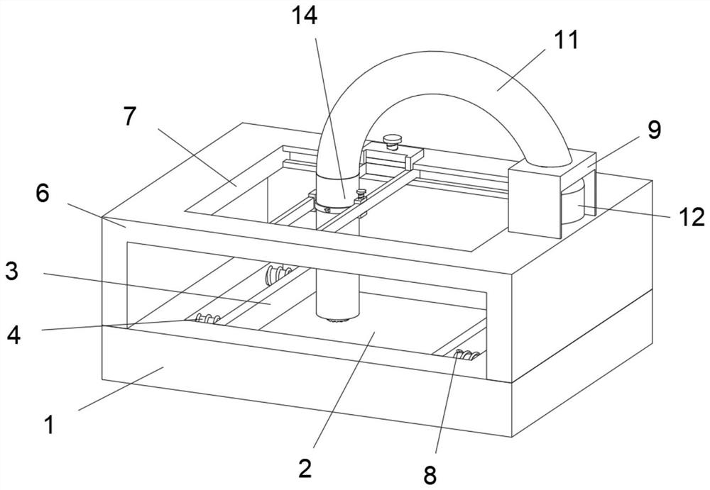
[0004] However, the prior art at least still has the following technical problems unresolved: 1) Although the existing device has strengthened the grinding adequacy of the sample, it cannot accurately limit the grinding position of the chip, which will easily cause the mixture in the peeling There are ground samples in the non-faulty area, which will have a great impact on the subsequent analysis results, which is not conducive to the staff to accurately determine the cause of the chip failure. 2) and the collection of the peeled powder in the existing device is only manual collection , this method not only has greater difficulty in operation, but also easily causes impurities such as dust attached to human hands to fall into the powder, causing analysis errors

Method used


Image

  • Chip sample delayering grinding method
  • Chip sample delayering grinding method
  • Chip sample delayering grinding method

Examples


Embodiment Construction

[0034]In describing the present invention, it should be understood that the terms "center", "longitudinal", "transverse", "length", "width", "thickness", "upper", "lower", "front", " Orientation indicated by rear, left, right, vertical, horizontal, top, bottom, inside, outside, clockwise, counterclockwise, etc. The positional relationship is based on the orientation or positional relationship shown in the drawings, and is only for the convenience of describing the present invention and simplifying the description, rather than indicating or implying that the referred device or element must have a specific orientation, be constructed and operated in a specific orientation, Therefore, it should not be construed as limiting the invention.

[0035] In the description of the present invention, "plurality" means two or more, unless otherwise specifically defined.

[0036] In the description of the present invention, it should be noted that, unless otherwise specified and limited, th...


PUM


Abstract

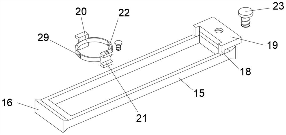
The invention discloses a chip sample delayering grinding method, and belongs to the field of chip test and analysis. The chip sample delayering grinding method is implemented based on a chip sample grinding device. The chip sample grinding device comprises a base, wherein a supporting frame is arranged on the upper side of the base, a through groove is formed in the position, opposite to a chip groove, of the middle of the top face of the supporting frame, a fixing box is arranged on the right side of the top face of the supporting frame, a threaded hole is formed in the middle of the top face of the fixing box, a metal hose is connected with the upper end of the threaded hole, a collecting bottle is arranged in the fixing box, external threads are arranged on the outer wall of the open end of the collecting bottle, a filter screen is embedded in the middle of the bottom face of the collecting bottle, and a fixed-point sampling assembly is arranged below the left side of the metal hose. In this way, the accuracy of the grinding sampling work of the fault area of the chip is improved, samples in other areas are prevented from being mixed with the sample, the effectiveness of analysis results is improved, and great help is provided for workers to analyze the cause of the fault of the chip.

Description

technical field [0001] The invention relates to the field of chip testing and analysis, and more specifically relates to a grinding method for chip sample degradation. Background technique [0002] With the development of the electronics industry, chips are used more and more widely. In chip testing and analysis, it is usually necessary to perform failure analysis on problematic sample chips. Failure analysis usually uses chip samples to be ground, and the positioning point or fault area is gradually analyzed. The layer is ground and peeled off, and the failure mechanism is observed to analyze the cause of failure. [0003] After searching, the patent with the publication number CN107738141A discloses a grinding method for chip sample degradation, through the combination of the imitation chip and the sample chip and the curing glue, the contact area during grinding is increased, and the curing glue is used to fill the imitation chip and the sample chip The gap between the s...

Claims


Application Information

Patent Timeline
Patent Type & Authority Applications(China)
IPC IPC(8): B24B1/00B24B37/10B24B37/34G01N1/28
CPCB24B1/00B24B37/042B24B37/10B24B37/34G01N1/286G01N2001/2866
Inventor 吴碧云
Owner 吴碧云
Learn More