
Transformer iron core clamping and carrying device

A transformer core and handling device technology, which is applied in the field of transformer production, can solve the problems of increasing the defective rate of transformer core production and damage of transformer core, etc., and achieve the effect of convenient cleaning, improving the yield rate, and reducing the probability of damage

Active Publication Date: 2021-06-01
嵊州市光宇实业有限公司 +1
View PDF6 Cites 0 Cited by
  • Summary
  • Abstract
  • Description
  • Claims
  • Application Information

AI Technical Summary

Problems solved by technology

[0002] The transformer is a device that uses the principle of electromagnetic induction to change the AC voltage. The main components are iron core and coil. The iron core of the transformer is composed of silicon steel sheets. Clamp and transport the transformer core between adjacent processes, but the clamp used to clamp the transformer core has no buffer space for the two splints used to clamp the transformer core during the process of clamping the transformer core. It is easy to cause the transformer core to be damaged due to excessive pressing, which increases the defective rate of transformer core production

Method used


Image

  • Transformer iron core clamping and carrying device
  • Transformer iron core clamping and carrying device
  • Transformer iron core clamping and carrying device

Examples


specific Embodiment approach

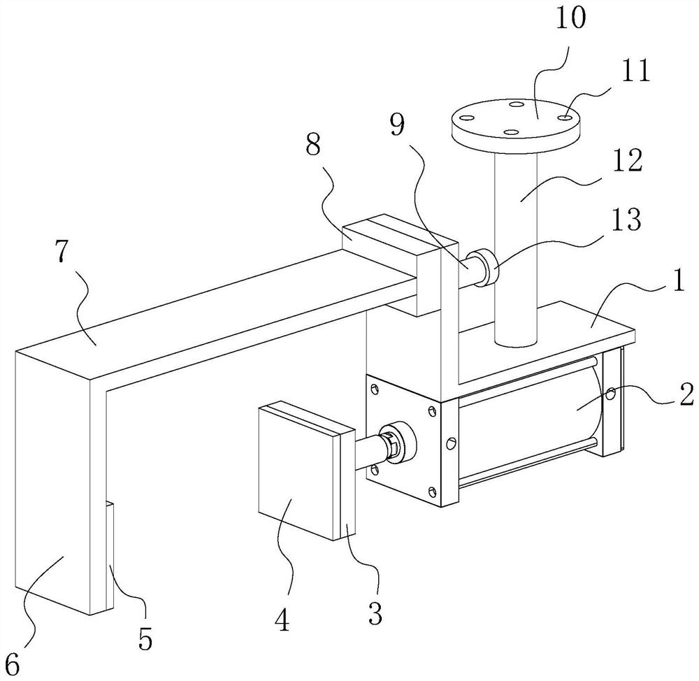
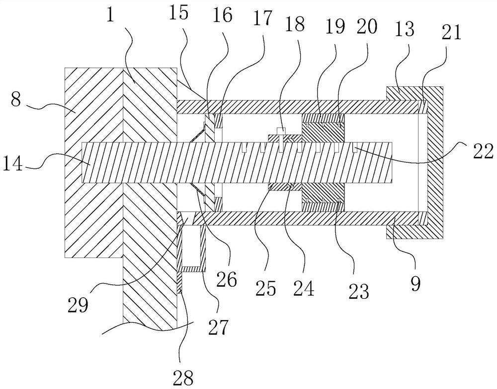
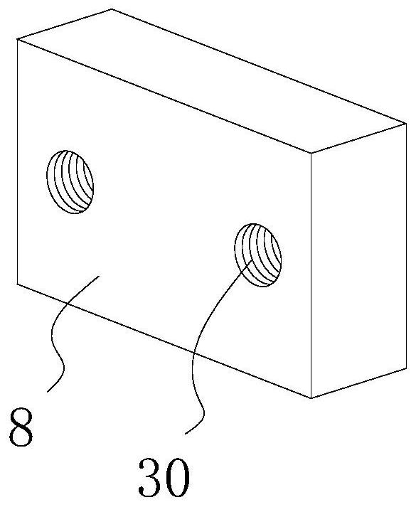
[0042] Specific implementation: Insert the two connecting rods 14 on the connecting seat 8 into the two cylinders 9 respectively, then screw the threaded cap 13 on the cylinder 9 to realize the blocking of one end of the cylinder 9, and then isolate the disc The ring 20 and the rubber ring 19 work together to divide the inner space of the cylinder body 9 into two parts. Since the gas volume between the isolation disc ring 20 and the threaded cover 13 remains unchanged, the isolation disc ring 20 is restricted under the action of the internal and external pressure difference. In the cylinder body 9 and does not slide randomly, the connection between the connecting seat 8 and the carrier plate 1 is realized. When the cylinder 2 drives the movable splint 3 and the fixed splint 6 to clamp the transformer iron core, it is affected by the reaction force of the transformer iron core. , the fixed splint 6 transmits the reaction force to the connecting rod 14 through the connecting plat...


PUM


Abstract

The invention relates to the technical field of transformer production, in particular to a transformer iron core clamping and carrying device. The transformer iron core clamping and carrying device comprises a carrier plate, a transversely-arranged air cylinder is installed on the lower surface of the carrier plate, a connecting base is installed on the vertical portion of the carrier plate, and a transversely-arranged connecting plate is installed on the face, away from the carrier plate, of the connecting base; two horizontally-arranged connecting rods are symmetrically installed on the face, facing the carrier plate, of the connecting base, inserting holes matched with the connecting rods are formed in the carrier plate, one ends of the connecting rods penetrate through the inserting holes and extend into a barrel, and the outer surface of the end, away from the carrier plate, of the barrel is in threaded connection with a threaded cover; and isolation disc rings with adjustable positions are installed on the connecting rods, and rubber rings fixedly connected with the isolation disc rings are arranged on the isolation disc rings in a sleeving mode.Compared with the prior art, the transformer iron core clamping and carrying device has the following beneficial effects that the purpose of buffering protection is achieved, and the probability that a transformer iron core is damaged due to excessive pressing is reduced.

Description

technical field [0001] The invention relates to a clamping and conveying device for a transformer iron core, which belongs to the technical field of transformer production. Background technique [0002] The transformer is a device that uses the principle of electromagnetic induction to change the AC voltage. The main components are iron core and coil. The iron core of the transformer is composed of silicon steel sheets. Clamp and transport the transformer core between adjacent processes, but the clamp used to clamp the transformer core has no buffer space for the two splints used to clamp the transformer core during the process of clamping the transformer core. It is easy to cause the transformer iron core to be damaged due to excessive pressing, which increases the defective rate of transformer iron core production. Contents of the invention [0003] In view of the deficiencies in the prior art, the purpose of the present invention is to provide a transformer iron core c...

Claims


Application Information

Patent Timeline
Patent Type & Authority Applications(China)
IPC IPC(8): B65G47/90
CPCB65G47/90
Inventor 何泽平
Owner 嵊州市光宇实业有限公司
Learn More