Waterproof structure of drainage type tunnel primary support system and construction method thereof

A technology for primary support and waterproof structures, applied in tunnels, tunnel linings, drainage, etc., can solve the problems of low cost, poor implementation effect, and inability to effectively release the water pressure on the back of the wall.

Active Publication Date: 2021-06-01
POWERCHINA CHENGDU ENG
View PDF15 Cites 6 Cited by
  • Summary
  • Abstract
  • Description
  • Claims
  • Application Information

AI Technical Summary

Problems solved by technology

[0009] The existing tunnel composite lining drainage technology cannot actively release the backwater pressure of the wall effectively, and can only passively wait for the pressurized wat

Method used


Image

  • Waterproof structure of drainage type tunnel primary support system and construction method thereof
  • Waterproof structure of drainage type tunnel primary support system and construction method thereof
  • Waterproof structure of drainage type tunnel primary support system and construction method thereof

Examples


Embodiment 1

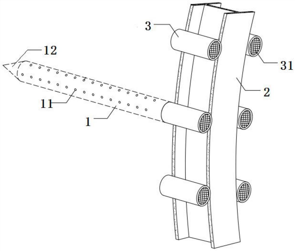
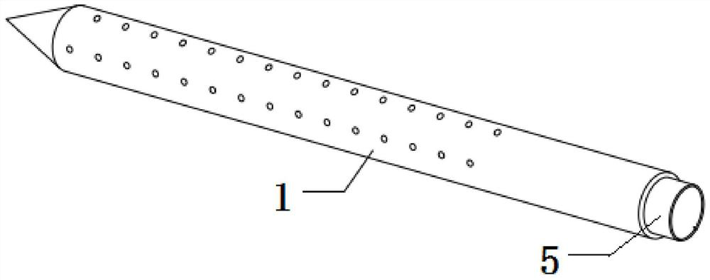
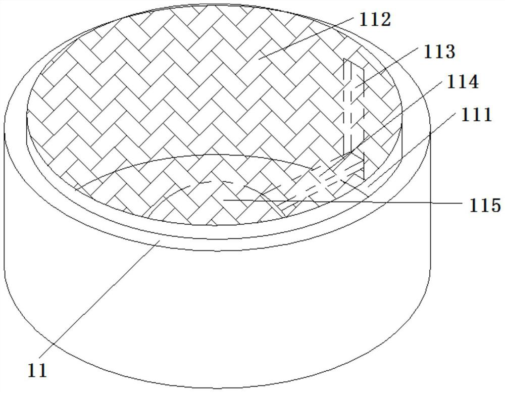
[0041] see figure 2 , 6 , a waterproof structure for the primary support system of a drainage type tunnel, comprising an outer tube 1 and an inner tube 5, the inner tube 5 can be extended into the inside of the outer tube 1 and pulled out, and the outer tube 1 The inner wall is in contact with the outer wall of the inner pipe 5, and the outer pipe 1 is provided with a water inlet hole 11, and the inner pipe 5 can rotate in the outer pipe 1 to realize the connection between the water inlet hole 11 and the inner pipe 1. The water inlet 52 on the pipe 5 is selectively communicated, and the inner pipe 5 is provided with a Tesla valve-shaped diversion chamber 51 communicating with the water inlet 52 of the inner pipe 5, and the diversion chamber 51 can be Under the action of speeding up the water flow out of the outer tube 1.

[0042] Wherein, the contact between the inner wall of the outer tube 1 and the inner wall of the inner tube 5 can prevent water from entering from the wate...

Embodiment 2

[0066] Embodiment 2 is a construction method for a waterproof structure of a drainage type tunnel primary support system proposed on the basis of Embodiment 1, and the steps are as follows:

[0067]S1: Insert the inner tube 5 into the inside of the outer tube 1, so that the water inlet 11 on the outer tube 1 and the water inlet 52 on the inner tube 5 are in a closed state; Pipe 1 is drilled into the rock formation at a certain angle;

[0068] S2: Rotate the inner tube 5 again, so that the water inlet 52 communicates with the water inlet hole 11 on the outer tube 1, and water can flow into the diversion chamber 51 of the inner tube 5;

[0069] S3: Fix the outer pipe 1, pull out the inner pipe 5 after no water flows out from the inner pipe 5; then inject grout into the outer pipe 1.

[0070] In actual implementation, specifically:

[0071] S1: The surface of the tunnel is excavated and cleared, the initial spraying in the tunnel (the initial support is divided into initial spr...


PUM


Abstract

The invention discloses a waterproof structure of a drainage type tunnel primary support system and a construction method thereof, and relates to the technical field of tunnel water seepage disposal. The inner wall of an outer pipe is arranged to be in contact with the outer wall of an inner pipe, and the problem that external impurities enter the outer surface of the inner pipe and block the inner wall of the outer pipe can be prevented; a water inlet hole is formed in the outer pipe, and the inner pipe can rotate in the outer pipe, so that the water inlet hole selectively communicates with a water inlet in the inner pipe; the outer pipe and the inner pipe can be used as anchor rods inserted into a rock mass, so that the bearing capacity of the rock mass is provided; and water can actively flow into the outer pipe, the wall back water pressure is effectively released, the outer pipe can be used for grouting reinforcement of tunnel surrounding rock, and the outer pipe and the inner pipe are combined with an existing waterproof layer and a drainage pipe system communicated in all directions in the existing design and correspond to each other, so that the stability of a waterproof and drainage system of a tunnel in the operation period is better ensured.

Description

technical field [0001] The invention relates to the technical field of tunnel water seepage treatment, in particular to a waterproof structure and a construction method of a drainage type tunnel primary support system. Background technique [0002] At present, in the construction of most mountain tunnels in Southwest my country, composite lining tunnels are constructed by mining method (artificial drilling and blasting method). According to the current "Code for Design of Highway Tunnels, Volume 1 Civil Engineering JTG3370.1-2018", the main design ideas for waterproofing and drainage of composite linings for mountain tunnels in the industry are as follows: [0003] (1) A waterproof layer and a drainage pipe system connected in all directions are set between the primary support of the tunnel and the secondary lining: the waterproof layer is a combination of waterproof board and non-woven fabric; the drainage pipe is generally a combination of perforated corrugated pipe and PV...

Claims


Application Information

Patent Timeline
IPC IPC(8): E21D11/38E21D11/18E21D11/10E21F16/02
CPCE21D11/38E21D11/18E21D11/10E21F16/02
Inventor 陈诚王建黄鹏
Owner POWERCHINA CHENGDU ENG
Why Eureka
Try Eureka