
Centrifugal partial pressure linkage stirrer

A mixer and centrifugal technology, applied in the field of centrifugal partial pressure linkage mixer, can solve the problems of not being able to separate old grass, catalyzing into fertilizer, not saving farm costs, etc.

Inactive Publication Date: 2021-06-04
崔茜
View PDF0 Cites 0 Cited by
  • Summary
  • Abstract
  • Description
  • Claims
  • Application Information

AI Technical Summary

Problems solved by technology

[0002] The centrifugal mixer is to stir the objects at a uniform speed through the action of centrifugation. Since there are herbivores planted on the farm, the wind shells are swept across the surface of the herbivores. Due to the different heights of the herbivores, the mature herbivores have a higher height and are relatively The height of tender herbivores is medium, and the height of freshly germinated herbivores is the lowest. The existing centrifugal mixers used in farms cannot automatically cut the grasses, and the existing centrifugal mixers used in farms cannot separate old grasses and Catalysis into fertilizer cannot save the cost of the farm. Therefore, it is necessary to design a centrifugal partial pressure linkage mixer with strong practicability and save the fertilizer cost of the farm.

Method used


Image

  • Centrifugal partial pressure linkage stirrer
  • Centrifugal partial pressure linkage stirrer
  • Centrifugal partial pressure linkage stirrer

Examples


Embodiment Construction

[0020] The following will clearly and completely describe the technical solutions in the embodiments of the present invention with reference to the accompanying drawings in the embodiments of the present invention. Obviously, the described embodiments are only some, not all, embodiments of the present invention. Based on the embodiments of the present invention, all other embodiments obtained by persons of ordinary skill in the art without making creative efforts belong to the protection scope of the present invention.

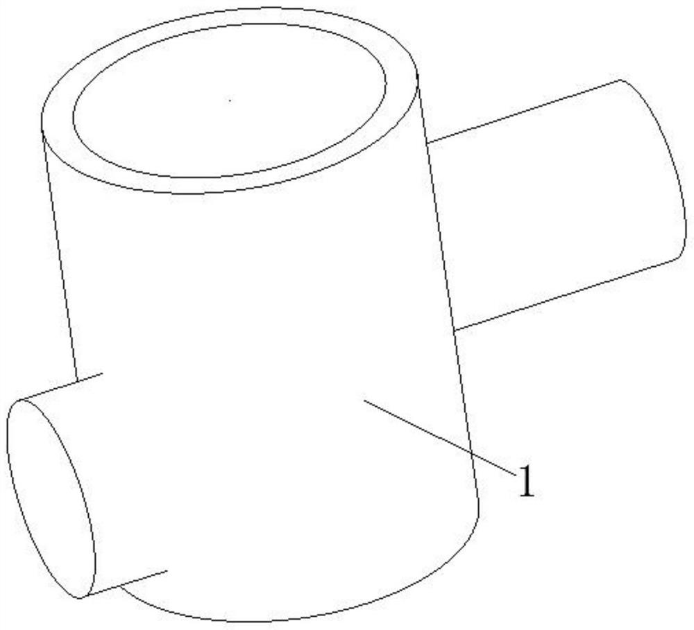
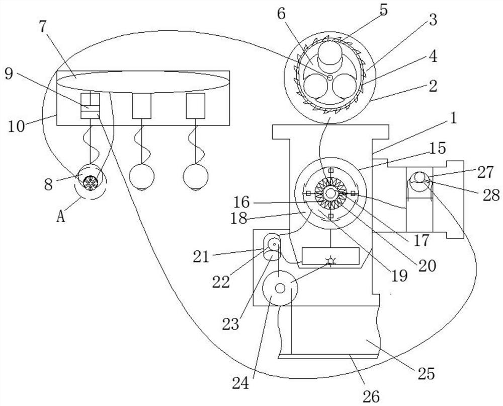
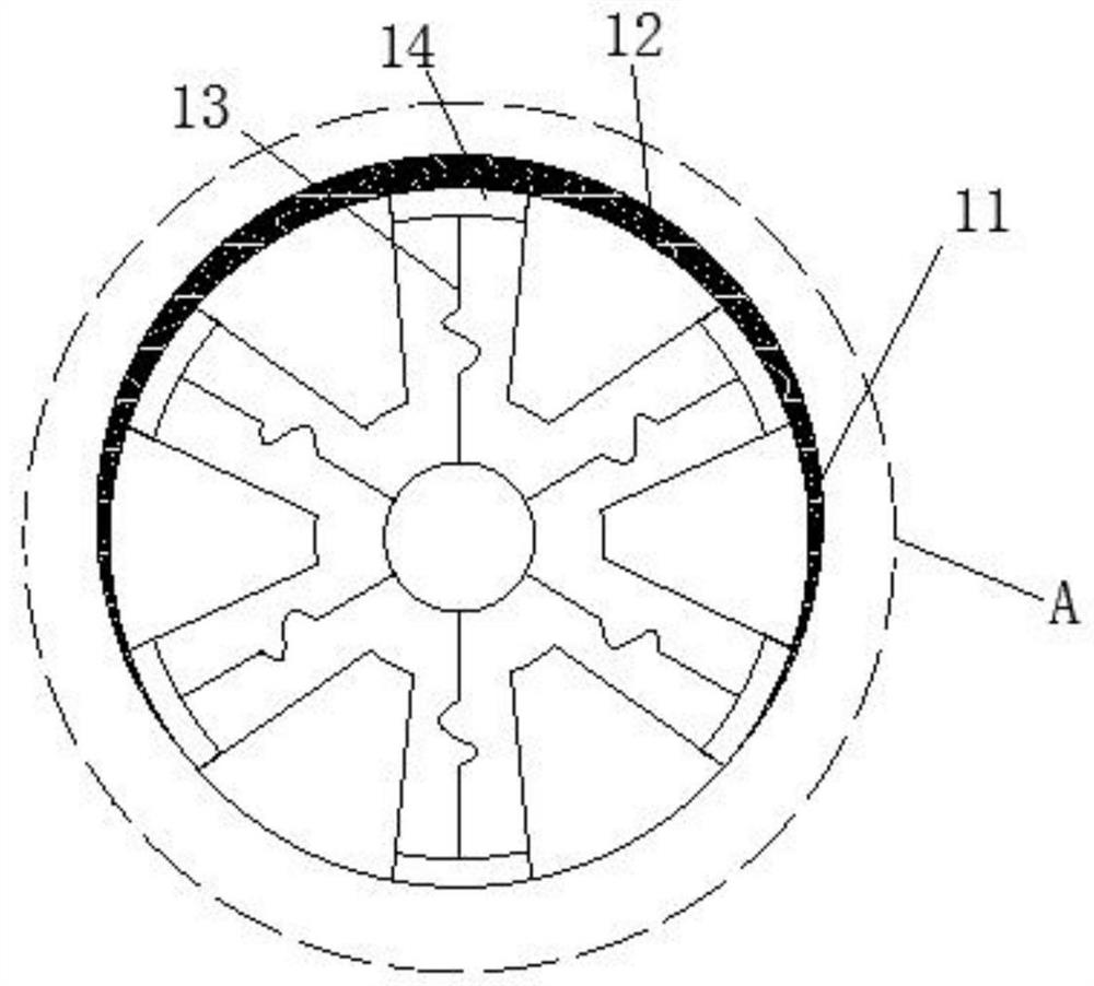
[0021] see Figure 1-3 , the present invention provides a technical solution: a centrifugal partial pressure linkage mixer, including a centrifugal cylinder 1, characterized in that: the left side of the centrifugal cylinder 1 is provided with an identification mechanism, and the top of the centrifugal cylinder 1 is provided with a cutting mechanism to identify The mechanism and the cutting mechanism are connected by pipelines. A separation mechanism is arrang...


PUM


Abstract

The invention discloses a centrifugal partial pressure linkage stirrer which comprises a centrifugal cylinder and is characterized in that an identification mechanism is arranged on the left side of the centrifugal cylinder; a cutting mechanism is arranged above the centrifugal cylinder; the identification mechanism and the cutting mechanism are connected through a pipeline; a separation mechanism is arranged in the middle of the interior of the centrifugal cylinder; the separation mechanism is connected with the cutting mechanism through a pipeline; the cutting mechanism is connected with the identification mechanism through a pipeline; a feeding mechanism is arranged on the lower portion of the interior of the centrifugal cylinder; the feeding mechanism is connected with the separation mechanism through a pipeline; the identification mechanism comprises a wind shell; a wind bag is arranged on the upper portion of the interior of the wind shell; a plurality of storage cavities are formed in the lower portion of the wind bag; pistons are arranged in the multiple storage cavities; and elastic telescopic pipes are arranged on one sides of the pistons. The centrifugal partial pressure linkage stirrer has the characteristics of being strong in practicability and capable of saving the fertilizer cost of a breeding farm.

Description

technical field [0001] The invention relates to the technical field of mixers, in particular to a centrifugal partial pressure linkage mixer. Background technique [0002] The centrifugal mixer is to stir the objects at a uniform speed through the action of centrifugation. Since there are herbivores planted on the farm, the wind shells are swept across the surface of the herbivores. Due to the different heights of the herbivores, the mature herbivores have a higher height and are relatively The height of tender herbivores is medium, and the height of freshly germinated herbivores is the lowest. The existing centrifugal mixers used in farms cannot automatically cut the grasses, and the existing centrifugal mixers used in farms cannot separate old grasses and Catalysis into fertilizer cannot save the cost of the farm. Therefore, it is necessary to design a centrifugal partial pressure linkage mixer with strong practicability and save the fertilizer cost of the farm. Contents...

Claims


Application Information

Patent Timeline
IPC IPC(8): A01F29/02A01F29/09A01F29/16B01F7/00B01F13/10
CPCA01F29/02A01F29/09A01F29/095A01F29/16B01F27/115B01F33/83B01F2101/18
Inventor 崔茜
Owner 崔茜
Learn More