Irrigation device for landscaping

An irrigation device and landscaping technology, applied in watering devices, horticulture, applications, etc., can solve problems such as the inability to ensure sufficient water intake, small irrigation range, and low efficiency, and achieve manpower saving, manpower saving, and water pumping volume sufficient effect

Pending Publication Date: 2021-06-04
郑玉民
View PDF0 Cites 3 Cited by
  • Summary
  • Abstract
  • Description
  • Claims
  • Application Information

AI Technical Summary

Problems solved by technology

[0005] In order to overcome the disadvantages of manually pumping in and pushing out water in the prior art, the efficiency is low, the scope of irrigation is small, the state of manually maintaining the water inlet is open, the waste is troublesome, and the amount of water pumped in cannot be guaranteed to be sufficient. Technical problem: provide an automatic pumping in and out Spray water, automatically adjust the water spray distance, open the water inlet while pumping water, and ensure sufficient water pumping. It is an irrigation device for landscaping

Method used


Image

  • Irrigation device for landscaping
  • Irrigation device for landscaping
  • Irrigation device for landscaping

Examples


Embodiment 1

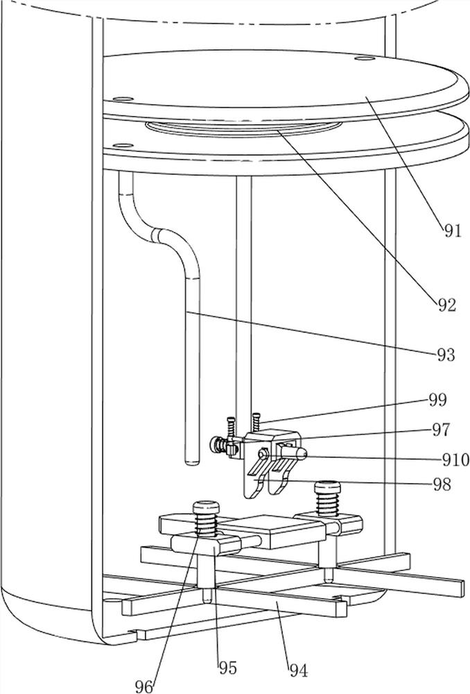
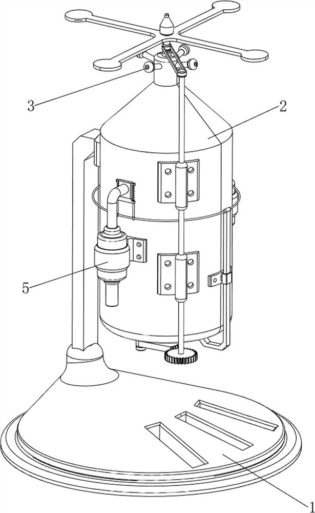
[0029] An irrigation device for landscaping such as figure 1 , figure 2 , image 3 and Figure 4 As shown, it includes a foot 1, an installation frame 2, a water spray head 3, a pressurizing mechanism 4, and a water inlet mechanism 5. The upper right side of the foot 1 is connected to the installation frame 2, and the upper part of the installation frame 2 is connected with four water sprays at even intervals. The head 3 is provided with a pressurizing mechanism 4 inside the installation frame 2, and a water inlet mechanism 5 is provided at the middle of the outside of the installation frame 2.

[0030] The pressurizing mechanism 4 includes a first slide bar 41, a squeeze plate 42, a push bar 43 and a first spring 44. The first slide bar 41 is symmetrically connected between the upper and lower sides of the installation frame 2, and the first slide bar 41 is slidingly connected with an extruding plate 42, and a first spring 44 is connected between the extruding plate 42 an...

Embodiment 2

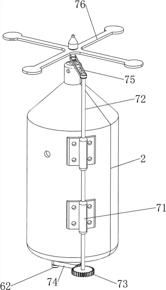
[0034] On the basis of Example 1, such as figure 1 , Figure 5 , Image 6 , Figure 7 and Figure 8 As shown, a driving mechanism 6 is also included, and the driving mechanism 6 includes a motor 61, a first rotating shaft 62, a second bracket 63, a space cam 64, a first transmission assembly 65, a first sliding sleeve 66, a second sliding rod 67 and The third spring 68, a motor 61 is installed on the lower front side of the installation frame 2, and the first rotating shaft 62 is connected to the lower side of the output shaft of the motor 61. The first rotating shaft 62 passes through the installation frame 2 and is connected with the installation frame 2 in a rotational manner. A second bracket 63 is connected to the rear side of the lower part of the frame 2, and a space cam 64 is rotatably connected to the middle part of the front side of the second bracket 63, and a first transmission assembly is connected between the lower side of the transmission shaft of the space c...


PUM


Abstract

The invention relates to an irrigation device, in particular to an irrigation device for landscaping. According to the irrigation device for landscaping, water is pumped and sprayed out automatically, the water spraying distance is adjusted automatically, a water inlet is opened while water is pumped in, and the situation that the water pumping amount is sufficient is guaranteed. The irrigation device for landscaping comprises supporting legs, four water sprayers, a pressurizing mechanism and a water inlet mechanism; one sides of the upper parts of the supporting legs are connected with a mounting frame; the four water sprayers are uniformly connected to the upper part of the mounting frame at intervals; the pressurizing mechanism is arranged in the mounting frame; and the water inlet mechanism is arranged in the middle of the outer side of the mounting frame. A motor is started to drive a space cam to rotate, a second sliding rod is driven to move up and down, then a pushing rod and an extrusion plate are driven to move up and down, the effects of automatically driving the extrusion plate to move up and down and repeatedly absorbing and spraying water are achieved, and manpower is saved.

Description

technical field [0001] The invention relates to an irrigation device, in particular to an irrigation device for landscaping. Background technique [0002] Garden irrigation refers to supplementing the soil moisture required for the growth of garden plants, using various methods to spray and irrigate the soil of garden green spaces, so that green plants can replenish water, better perform photosynthesis, and create a better green environment. [0003] The existing landscaping irrigation technology is mainly through the user manually pumping in the water source and then pushing it out, and spraying it on the garden land. However, manually pumping in and pushing out the water is time-consuming, labor-intensive, and inefficient. The distance is fixed, so that the irrigation area is small. When pumping water, the user needs to manually maintain the state of moving the baffle in the water inlet pipe. [0004] How to design a kind of automatic pumping and spraying water, automatic...

Claims


Application Information

Patent Timeline
Patent Type & Authority Applications(China)
IPC IPC(8): A01G25/02
CPCA01G25/02
Inventor 郑玉民
Owner 郑玉民
Why Eureka
Try Eureka