A field insect trapping device

An insect trapping technology, which is applied in the field of insect trapping, can solve the problems of inconvenient removal, sticking of corpses on the light source, and high power consumption, so as to achieve good trapping effect and increase trapping effect

Active Publication Date: 2022-07-22
湖南天长农业科技发展有限公司 +1
View PDF0 Cites 0 Cited by
  • Summary
  • Abstract
  • Description
  • Claims
  • Application Information

AI Technical Summary

Problems solved by technology

[0004] 1. Now most of them use light trapping to catch insects in the wild. The trap is turned on at night and closed during the day. After the insect enters the trap, it is electrocuted to death through the internal power grid. The power grid needs to be turned on for a long time and is stable. Higher voltage requires more power consumption, and after electrocution, a small number of corpses will be glued to the light source, which requires regular maintenance and cleaning
[0005] 2. Most of the insects after electrocution will fall into the collection box, which needs to be removed and cleaned regularly, and the mosquito killer lamp is generally set at a higher place, which is extremely inconvenient to remove

Method used


Image

  • A field insect trapping device
  • A field insect trapping device
  • A field insect trapping device

Examples


Embodiment 1

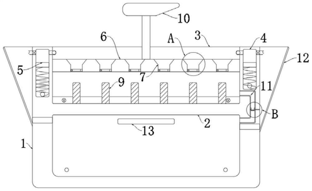
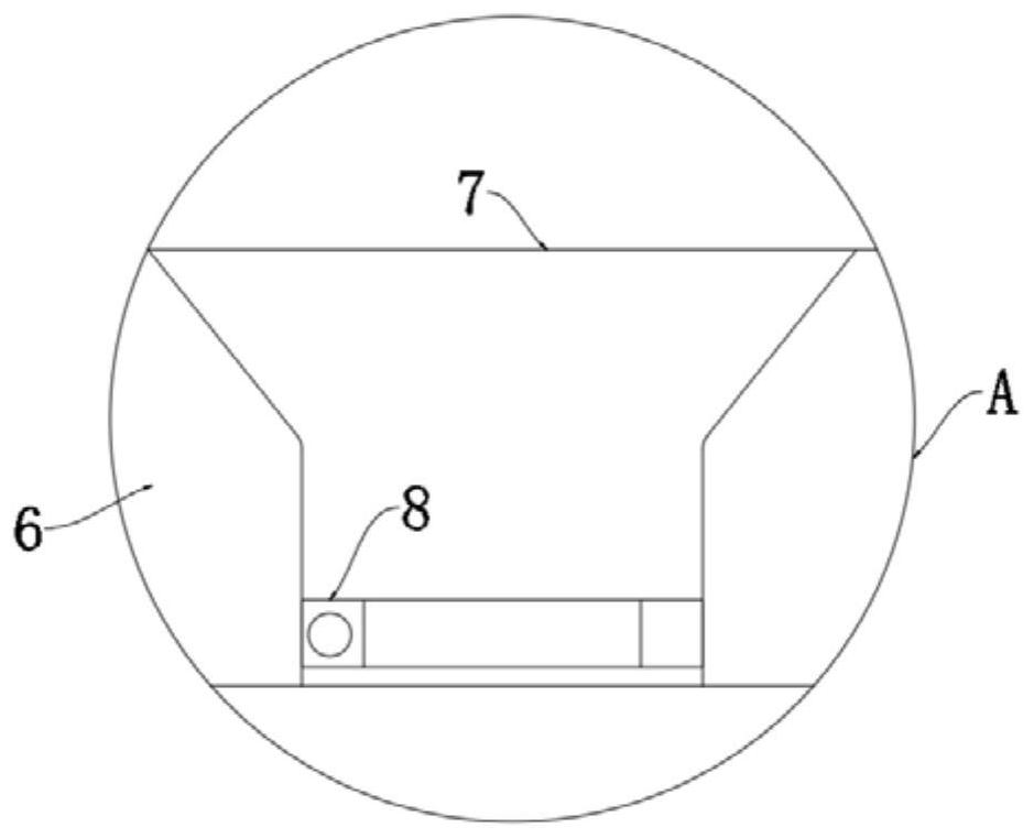
[0038] refer to Figure 1-3 , an insect trapping device for field use, comprising a treatment box 1, a water tank 2 is arranged in the treatment box 1, the left and right ends of the water tank 2 are provided with water replenishment pipes that are in sealing communication with the water tank 2, and both sides of the treatment box 1 are provided with water replenishment pipes The water collecting bucket 12 connected by the pipe seal, realizes that in rainy days, the rainwater is guided into the water tank 2, and the water in the water tank 2 is supplemented. When touching the water, the insect's wings become heavier, thus preventing the insect from flying out;

[0039] The left and right walls of the processing box 1 are provided with cavities 4, and the two cavities 4 are both sealed and slidably connected with a magnetic sliding plug 5, and the magnetic sliding plug 5 and the inner bottom of the cavity 4 are elastically connected by a first spring;

[0040] The upper end of...

Embodiment 2

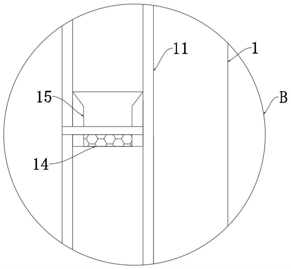
[0052] refer to Figure 4-5 , The difference between this embodiment and Embodiment 1 is that the processing box 1 is provided with an air storage chamber 16 on one side of the drain pipe 11, and a baffle is sealed and slidably connected in the air storage chamber 16; The lower end is provided with an installation port 17, a push plate 18 extending into the installation port 17 is fixedly connected to the baffle, and the baffle is elastically connected with the right side wall of the air storage cavity 16 through a second spring; the lower ends of the two cavities 4 are both The air-storage chamber 16 is sealed and communicated through the pipeline. The extension length of the push plate 18 is greater than the diameter of the drain pipe 11. The lower end surface of the push plate 18 is close to the upper end surface of the filter screen 14, which is beneficial to push out the insect corpses on the filter screen 14. During the downward movement of the magnetic sliding plug 5, t...


PUM


Abstract

The invention discloses an insect trapping device for field use, comprising a treatment box, a water tank is arranged in the treatment box, and a capture box containing a small amount of water is arranged on the upper side of the water tank; Both are provided with cavities, and the two cavities are sealed and slidably connected with magnetic slide plugs, and the magnetic slide plugs and the inner bottom of the cavities are elastically connected by a first spring; the upper end of the cavities is provided with a A water inlet pipe that communicates with the water tank, the water inlet pipe is provided with a one-way valve that only allows water to enter the cavity from the water tank; the upper end of the cavity is provided with a water outlet pipe that communicates with the capture tank, and the water outlet pipe is provided with only a A one-way valve that allows water to enter the capture box from the cavity; a magnetic slide plate matched with a magnetic slide plug is slidably connected in the capture box. The present invention has a reasonable structure, can capture wild insects, and can also automatically clean the device.

Description

technical field [0001] The invention relates to the technical field of insect trapping, in particular to a field insect trapping device. Background technique [0002] Insect traps are widely used in farms, farmhouses and homes to trap insects such as mosquitoes. The trapping methods include pheromone method, light method, sticking method, etc. Insect traps are also used in wild crops. Avoid excessive pests affecting the growth of crops. [0003] But the existing field insect traps also have some problems: [0004] 1. Now most of them use light trapping to capture wild insects. The traps are turned on at night and turned off during the day. After the insects enter the trap, they are electrocuted through the internal power grid. The power grid needs to be turned on for a long time to stabilize At higher voltages, more power is consumed, and after electrocution, there will be a problem that a small number of corpses will stick to the light source, which requires regular maint...

Claims


Application Information

Patent Timeline
Patent Type & Authority Patents(China)
IPC IPC(8): A01M1/04A01M1/00E03B3/02B01D29/64B01D29/01
CPCA01M1/04A01M1/00E03B3/02B01D29/6484B01D29/01A01M2200/012Y02A20/108
Inventor 黄振松
Owner 湖南天长农业科技发展有限公司
Why Eureka
Try Eureka