Automobile part stamping device

A stamping device and spare parts technology, applied in the direction of feeding device, positioning device, storage device, etc., can solve the problems of inconvenient control of the conveying position, low stamping efficiency, and decreased stamping effect of products

Pending Publication Date: 2021-06-04
重庆大江国立精密机械制造有限公司
View PDF16 Cites 1 Cited by
  • Summary
  • Abstract
  • Description
  • Claims
  • Application Information

AI Technical Summary

Problems solved by technology

[0003] However, in the existing spare parts processing process, it is often necessary to use a stamping device to stamp the parts. The current stamping device is generally simple in structure, and the parts need to be transported to the lower end of the stamping head manually or through a conveyor belt for stamping, which is artificially time-consuming. It is laborious, and it is inconvenient to control the conveying position when conveying with a conveyor belt. It is often necessary to ma

Method used


Image

  • Automobile part stamping device
  • Automobile part stamping device
  • Automobile part stamping device

Examples


Embodiment Construction

[0032] In order to further illustrate the various embodiments, the present invention provides accompanying drawings, which are part of the disclosure of the present invention, and are mainly used to illustrate the embodiments, and can be used in conjunction with the relevant descriptions in the specification to explain the operating principles of the embodiments, for reference Those of ordinary skill in the art should be able to understand other possible implementations and advantages of the present invention. The components in the figures are not drawn to scale, and similar component symbols are generally used to represent similar components.

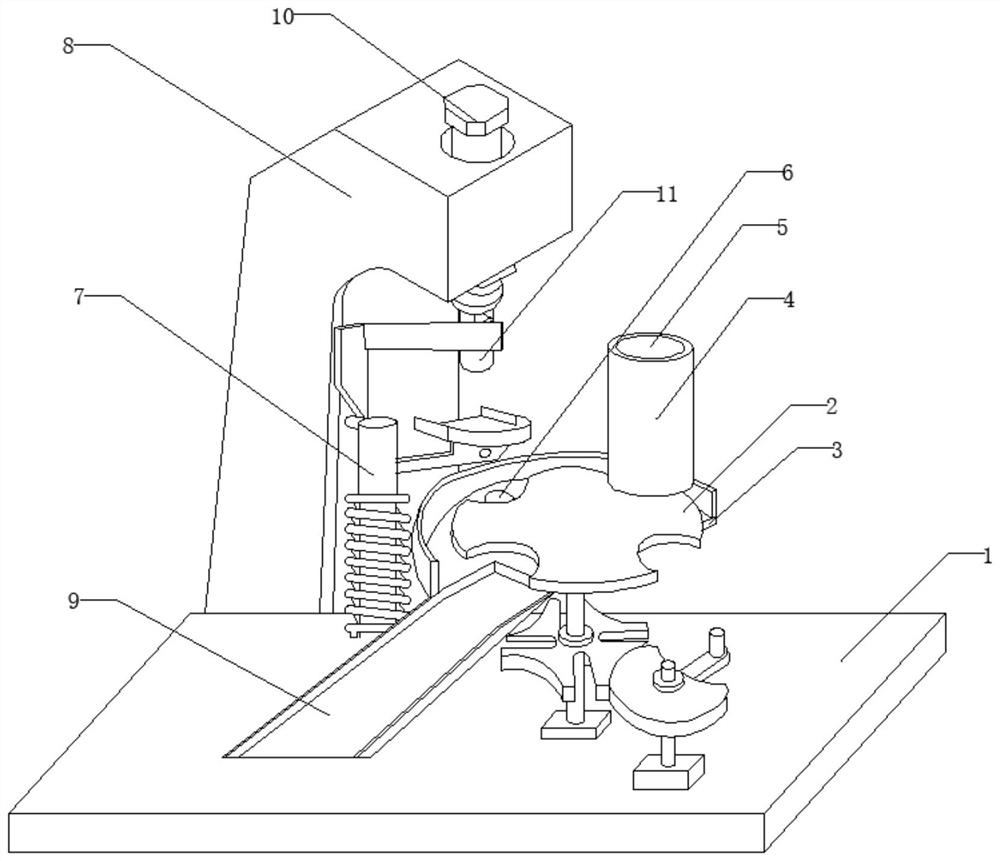
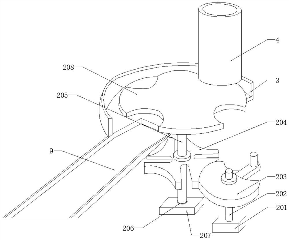
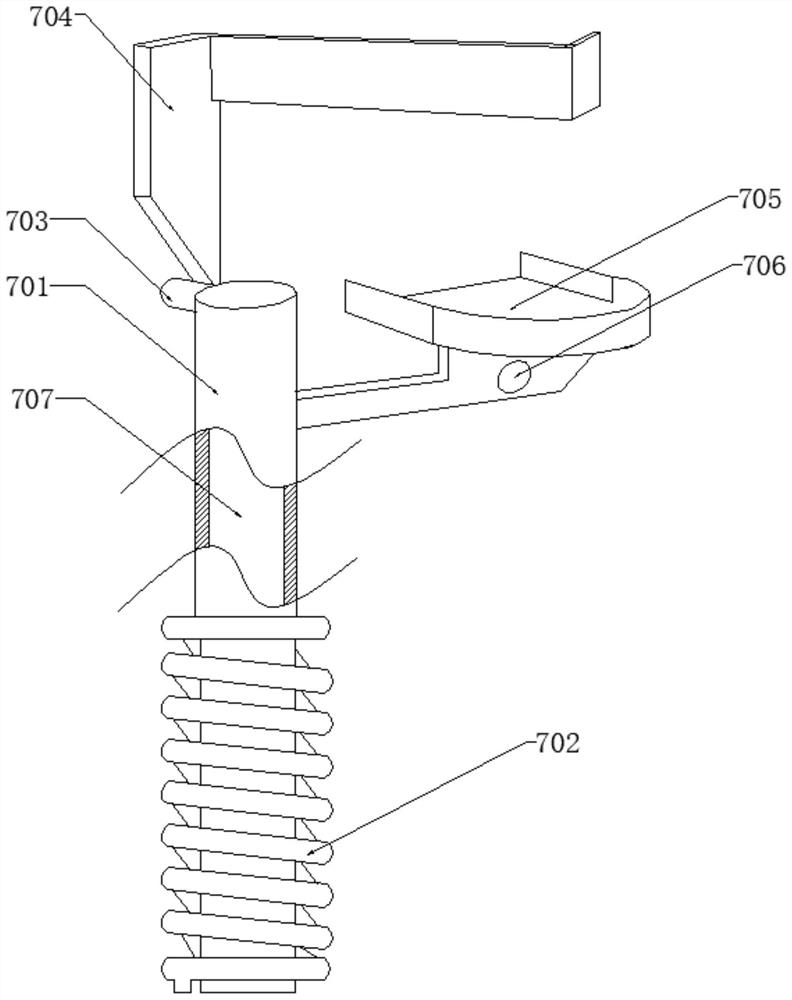
[0033] According to an embodiment of the present invention, a stamping device for auto parts is provided.

[0034] Now in conjunction with accompanying drawing and specific embodiment the present invention is further described, as Figure 1-7 As shown, the stamping device for auto parts according to the embodiment of the present invent...


PUM


Abstract

The invention discloses an automobile part stamping device which comprises a bottom plate, an adjusting mechanism is arranged at the top end of the bottom plate, a feeding disc is arranged on one side of the top end of the adjusting mechanism, a discharging groove is formed in the top end of the feeding disc, a feeding port is formed in the top end of the discharging groove, a lower die is arranged at the top end of the feeding disc, and a sweeping mechanism is arranged on one side of the adjusting mechanism. A punching machine is arranged on the side, away from the adjusting mechanism, of the sweeping mechanism, the sweeping mechanism and the punching machine are arranged at the top end of the bottom plate, and a discharging plate is arranged at the bottom end of the feeding disc. The automobile part stamping device has the beneficial effects that under the action of the adjusting mechanism, the discharging groove can evenly discharge materials at a constant speed, so that the working efficiency is improved, an obtained die can be directly discharged from the discharging plate under the action of a punching head of the punching machine and the lower die, and therefore collection of automobile parts is completed, and under the action of the sweeping mechanism, and after each time of stamping is finished, the sweeping mechanism is used for blowing and cleaning the surface of the lower die, so that sweeps of the lower die are cleaned away.

Description

technical field [0001] The invention relates to the technical field of stamping of auto parts, in particular to a stamping device of auto parts. Background technique [0002] Stamping is a forming processing method that applies external force to plates, strips, pipes and profiles by presses and molds to cause plastic deformation or separation to obtain workpieces (stamping parts) of required shape and size. Compared with castings and forgings, stamping parts have the characteristics of thinness, uniformity, lightness and strength. Stamping can produce workpieces with ribs, ribs, undulations or flanges that are difficult to manufacture by other methods to increase their rigidity. Due to the superiority of stamping, stamping has a wide range of applications in various fields of the national economy. For example, there are stamping processes in aerospace, aviation, military industry, machinery, agricultural machinery, electronics, information, railway, post and telecommunicat...

Claims


Application Information

Patent Timeline
IPC IPC(8): B21D22/08B21D43/16B21D43/20B08B5/02
CPCB21D22/08B21D43/16B21D43/20B08B5/02
Inventor 谭文斌王伟李华林
Owner 重庆大江国立精密机械制造有限公司
Why Eureka
Try Eureka