Circuit cutter for electronic circuit board welding and application method thereof

A technology for electronic circuit boards and wire cutters, which is applied in welding equipment, shearing devices, shearing machines, etc., can solve the problems of low efficiency, inability to cut wires, waste of electric energy, etc. in manual wire cutting, and achieve increased cleaning difficulty and fast wire cutting , the effect of reducing energy consumption

Inactive Publication Date: 2021-06-04
李秀
View PDF8 Cites 0 Cited by
  • Summary
  • Abstract
  • Description
  • Claims
  • Application Information

AI Technical Summary

Problems solved by technology

[0005] The purpose of the present invention is to solve the disadvantages of low efficiency of manual thread trimming, large workload, possible missing cuts and inability to cut during automatic thread trimming in the prior art, and the need for a large amount of electric power to drive and waste electric energy. A wire cutter for electronic circuit board welding and its application method

Method used


Image

  • Circuit cutter for electronic circuit board welding and application method thereof
  • Circuit cutter for electronic circuit board welding and application method thereof
  • Circuit cutter for electronic circuit board welding and application method thereof

Examples


Embodiment Construction

[0026] The following will clearly and completely describe the technical solutions in the embodiments of the present invention with reference to the accompanying drawings in the embodiments of the present invention. Obviously, the described embodiments are only some, not all, embodiments of the present invention.

[0027] In describing the present invention, it should be understood that the terms "upper", "lower", "front", "rear", "left", "right", "top", "bottom", "inner", " The orientation or positional relationship indicated by "outside", etc. is based on the orientation or positional relationship shown in the drawings, and is only for the convenience of describing the present invention and simplifying the description, rather than indicating or implying that the referred device or element must have a specific orientation, so as to Specific orientation configurations and operations, therefore, are not to be construed as limitations on the invention.

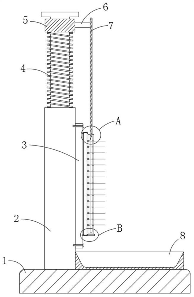
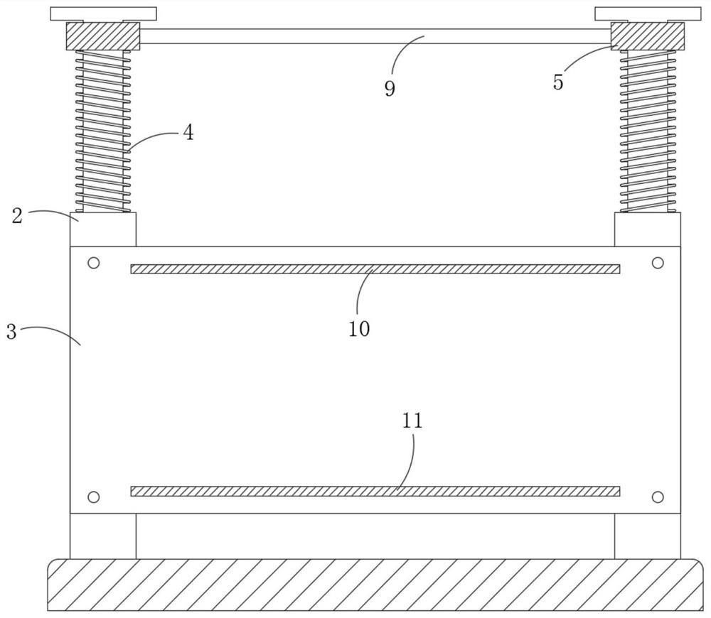
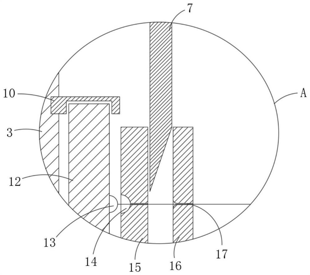
[0028] refer to Figure ...


PUM


Abstract

The invention discloses a circuit cutter for electronic circuit board welding and an application method. The circuit cutter comprises a base, wherein two telescopic rods are symmetrically installed on the base, pressing sleeves are arranged at the telescopic ends of the two telescopic rods in a sliding and sleeving mode, a connecting rod is welded to each pressing sleeve, and a circuit cutting blade is jointly and fixedly installed on the two connecting rods. A fixing plate is jointly installed at the fixing ends of the two telescopic rods, an upper fixing strip and a lower fixing strip are symmetrically installed at the upper end and the lower end of the fixing plate correspondingly, and fixing clamping grooves are formed in the upper fixing strip and the lower fixing strip correspondingly. According to the circuit cutter, a circuit board is fixed through the upper fixing strip and the lower fixing strip, weld legs are fixed through a left side plate and a right side plate, the weld legs are cut off through the circuit cutting blade, circuit cutting can be faster through one-time cutoff, cutting of the circuit cutting blade can be more flush through a synchronous rod, the fixing plates with different specifications can be conveniently replaced to fix the circuit boards with different specifications through screw assembly and disassembly of the fixing plate and the two telescopic rods, and the applicability of the device is improved.

Description

[0001] This application is a divisional application with an application date of September 2, 2019 and an application number of CN 201910821447.8, whose invention name is a wire cutter for electronic circuit board welding. technical field [0002] The invention relates to the field of circuit board production, in particular to a wire cutter for welding electronic circuit boards and a method for using the same. Background technique [0003] With the rapid development of science and technology, the replacement speed of electronic products is getting faster and faster. In the production process of electronic products, the most important thing is the circuit board of electronic products. The pins or pins of the device are soldered on the circuit board by soldering, but because there are many pins or pins on the soldered circuit board, they need to be cut before they can be used safely. [0004] The existing basic method of cutting pins is that employees use pliers to manually cut...

Claims


Application Information

Patent Timeline
Patent Type & Authority Applications(China)
IPC IPC(8): B23K3/08B23D15/04B23D33/02B23Q11/00
CPCB23K3/08B23D15/04B23D33/02B23Q11/0042
Inventor 李秀
Owner 李秀
Why Eureka
Try Eureka