Unlock instant, AI-driven research and patent intelligence for your innovation.
Automatic paper tube manufacturing device
What is Al technical title?
Al technical title is built by PatSnap Al team. It summarizes the technical point description of the patent document.
A paper tube, automatic technology, applied in the engineering field, can solve problems such as single function and low efficiency
Inactive Publication Date: 2021-06-04
赵凤玲
View PDF0 Cites 0 Cited by
Summary
Abstract
Description
Claims
Application Information
AI Technical Summary
This helps you quickly interpret patents by identifying the three key elements:
Problems solved by technology
Method used
Benefits of technology
Problems solved by technology
[0002] The paper tube making device is a common construction machine, but the general paper tube making device is manually operated, the efficiency is low, and the function is relatively single
Method used
Image
Click on the blue label to locate the original text in one second.
Reading with bidirectional positioning of images and text.
Examples
specific Embodiment approach 1
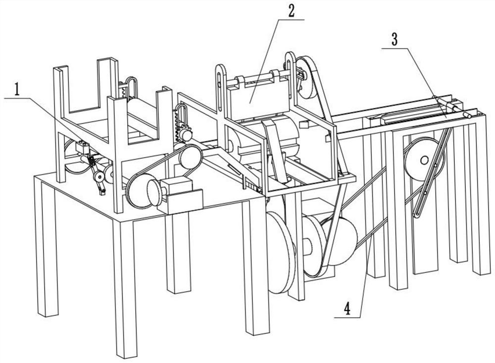
[0026] Combine below Figure 1-10 Description of the present embodiment, an automatic paper tube production device, including a paper separation device 1, a folding paper tube device 2, a peeling paper tube device 3, and a belt 4, the paper separation device 1 is connected with the folding paper tube device 2, Folding paper tube device 2 is connected with belt one 4, and peeling paper tube device 3 is connected with belt one 4.
specific Embodiment approach 2
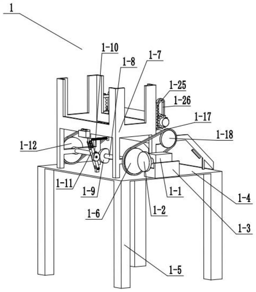
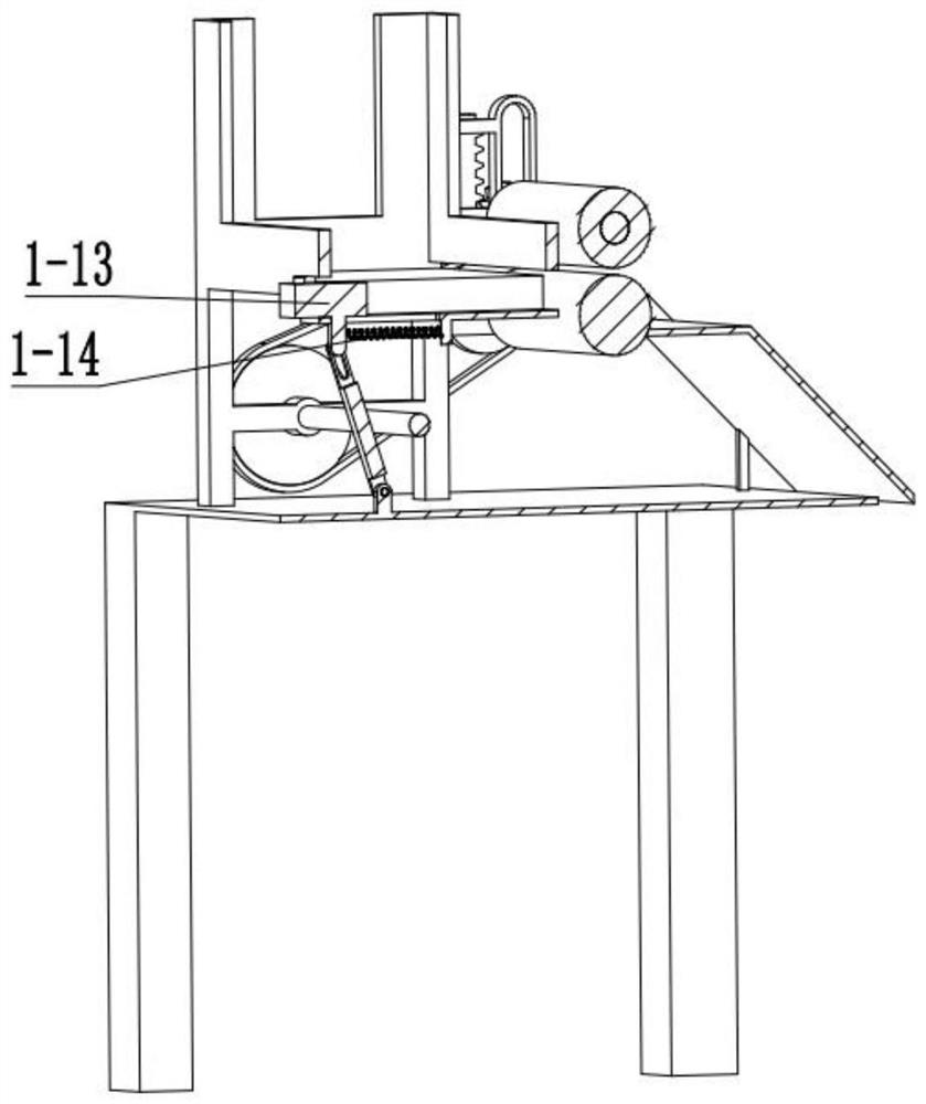
[0028] Combine below Figure 1-10Describe this embodiment, this embodiment will further explain Embodiment 1, the described paper separation device 1 includes a motor 1-1, a runner 1-2, a motor base 1-3, a base 1-4, and a tripod 1-5, runner two 1-6, upper frame 1-7, connecting column one 1-8, half runner 1-9, runner three 1-10, connecting rod one 1-11, runner four 1- 12. Slider 1-13, spring one 1-14, small cylinder 1-15, spring two 1-16, belt two 1-17, runner five 1-18, belt three 1-19, runner six 1- 20. Roller one 1-21, roller two 1-22, knob 1-23, gear one 1-24, straight tooth one 1-25, straight groove one 1-26, slideway 1-27, rubber brush 1- 28. Motor one 1-1 is fixedly connected with runner one 1-2, motor one 1-1 is slidingly connected with motor base 1-3, motor base 1-3 is fixedly connected with base 1-4, four tripods 1- 5 are all fixedly connected with the base 1-4, the first runner 1-2 is connected with the second runner 1-6, the base 1-4 is fixedly connected with the ...
specific Embodiment approach 3
[0031] Combine below Figure 1-10 Describe this embodiment, this embodiment will further explain the first embodiment, the origami tube device 2 includes motor two 2-1, runner seven 2-2, runner eight 2-3, connecting column five 2-4, Bracket three 2-5, belt five 2-6, runner nine 2-7, small cylinder two 2-8, connecting rod two 2-9, connecting block 2-10, straight groove two 2-11, connecting rod three 2 -12, connecting rod four 2-13, connecting rod five 2-14, small cylinder three 2-15, bracket two 2-16, paper tube mold 2-17, connecting column six 2-18, groove 2-19, Pulley two 2-20, small cylinder four 2-21, runner ten 2-22, small cylinder five 2-23, connecting rod six 2-24, straight groove five 2-25, straight groove six 2-26, small cylinder Ten 2-27, connecting column ten 2-28, gravity block 2-29, motor two 2-1 is fixedly connected with runner seven 2-2, and runner seven 2-2 cooperates with runner eight 2-3 to connect, turn Wheel eight 2-3 is fixedly connected with connecting c...
PUM
Abstract
The invention relates to the field of engineering, in particular to an automatic paper tube manufacturing device. The automatic paper tube manufacturing device can adapt to the thickness of paper sheets by changing the distance between two rollers. The operation speed of the device is changed to adapt to cooperation of all the devices. The position of a motor I in a motor base is changed, therefore the rotating speed of a rotating wheel II is changed, and the rotating speed of a connecting column I is changed. The rotating speed of a half rotating wheel is changed, therefore the reciprocating motion speed of a sliding block is changed, and the speed at which the paper sheets are pushed out of an upper frame body one by one is changed. Due to the fact that the speed of the rotating wheel II is changed, the rotating speed of a belt II is changed, the rotating speed of a rotating wheel V is changed, the rotating speed of a rolling wheel I is changed, and the speed of pushing out the paper sheets is changed. Therefore, the speed of the paper sheets entering a paper tube folding device in a matched mode can be controlled. Due to the fact that a gear I and a straight tooth I are in meshing transmission, the roller II is driven to move upwards or downwards, and the distance between the roller I and the roller II is changed to be matched with the thickness of the paper sheets.
Description
technical field [0001] The invention relates to an engineering field, in particular to an automatic paper tube making device. Background technique [0002] The paper tube making device is a common construction machine, but the general paper tube making device is manually operated, which is inefficient and has a single function. Contents of the invention [0003] The purpose of the present invention is to provide an automatic paper tube making device, which can adapt the thickness of the paper sheet by changing the distance between the two rollers; adapt the cooperation of each device by changing the operating speed of the device. [0004] The purpose of the present invention is achieved through the following technical solutions: [0005] An automatic paper tube making device, comprising a paper sheet separating device, a paper folding device, a peeling paper tube device, and a belt one, the paper separating device is connected with the folding paper tube device, the foldi...
Claims
Application Information
Patent Timeline
Application Date:The date an application was filed.
Publication Date:The date a patent or application was officially published.
First Publication Date:The earliest publication date of a patent with the same application number.
Issue Date:Publication date of the patent grant document.
PCT Entry Date:The Entry date of PCT National Phase.
Estimated Expiry Date:The statutory expiry date of a patent right according to the Patent Law, and it is the longest term of protection that the patent right can achieve without the termination of the patent right due to other reasons(Term extension factor has been taken into account ).
Invalid Date:Actual expiry date is based on effective date or publication date of legal transaction data of invalid patent.
