Air bearing compressor

An air bearing and compressor technology, applied in the field of compressors, can solve the problems of air disturbance, rotor tilt, low work efficiency, etc., and achieve the effects of reducing manufacturing and practical costs, increasing gas pressure, and improving work efficiency

Active Publication Date: 2021-06-04
广东智空动力科技有限公司
View PDF10 Cites 0 Cited by
  • Summary
  • Abstract
  • Description
  • Claims
  • Application Information

AI Technical Summary

Problems solved by technology

[0004] (1) Most of the high-pressure air generated by the high-speed rotation of the impeller in the air bearing compressor for fuel cells is discharged through the air outlet of the volute, and a small part is compressed into the air flow through the inclined hole A at the left end of the connecting sleeve. The high-pressure gas coming out of the air outlet B at the right end of the connecting sleeve is compressed in the gap between the rotor and the stator. When the rotor rotates at high speed, the high-pressure air not only acts as a lubricant, but also forms a gap between the surface of the stator and the rotor due to its viscosity. Large air mold pressure, thus forming a dynamic pressure to support the entire electric spindle; however, when the rotor rotates at a high speed, the air between the stator and the rotor in the air bearing will be disturbed, if only through the air between the stator and the rotor The air pressure on both sides of the air bearing is adjusted by using the gap, which will easily cause the air pressure on both sides of the air bearing to be inconsistent, so it is easy to cause deviations in the coaxiality of the rotor in the air bearing, such as causing the rotor to tilt, thereby affecting the air compressor. work adversely affected
[0005] 2. The air bearing compressor for the fuel cell can only achieve one-stage compression of the gas, and the work efficiency is low

Method used


Image

  • Air bearing compressor
  • Air bearing compressor
  • Air bearing compressor

Examples


Embodiment 1

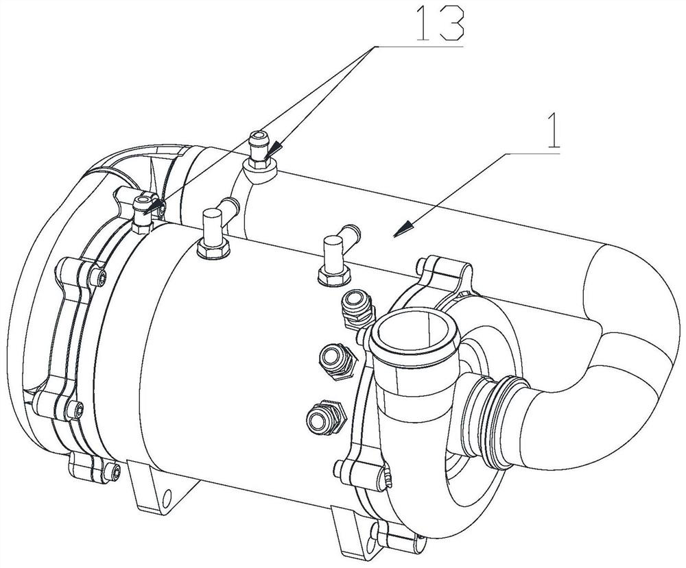
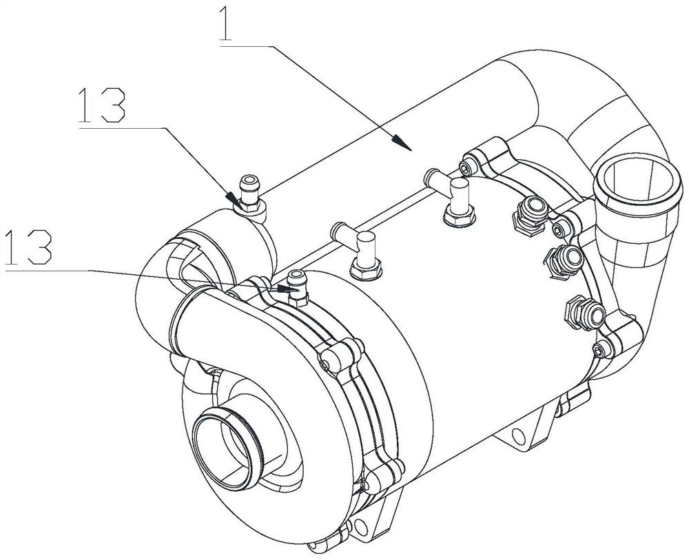
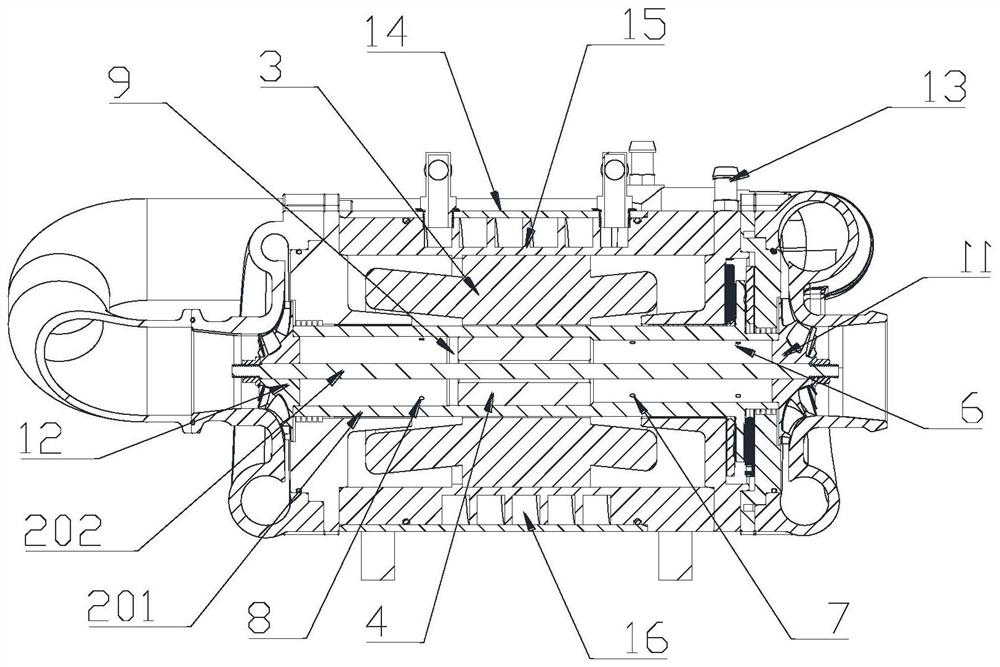
[0029] see Figure 1-Figure 4 , The air bearing compressor of the present invention includes a casing, a compression mechanism arranged in the casing, and a compression drive mechanism for driving the compression mechanism to work.

[0030] see Figure 1-Figure 4 , the compression mechanism includes a first compression member and a second compression member, wherein the first compression member and the second compression member are located on both sides of the housing; the housing is in contact with the first compression member A first compression cavity and a second compression cavity are respectively provided at corresponding positions of the second compression element, the first compression element is arranged in the first compression cavity; the second compression element is arranged in the second compression cavity; The gas outlet of the first compression chamber communicates with the gas inlet of the second compression chamber through a connecting pipe 1 .

[0031] see...

Embodiment 2

[0042] The difference between this embodiment and Embodiment 1 is that the first-stage impeller 11 or \and the second-stage impeller 12 are centrifugal compression impellers.

Embodiment 3

[0044] The difference between this embodiment and Embodiment 1 is that a communication groove for connecting the first cavity and the second cavity is provided in the rotating sleeve 202 , and the communication groove forms the second gas channel 10 .


PUM


Abstract

The invention discloses an air bearing compressor. The air bearing compressor comprises a shell, a compression mechanism and a compression driving mechanism; the compression mechanism comprises a first compression piece and a second compression piece; an air outlet of a first compression cavity communicates with an air inlet of a second compression cavity; the compression driving mechanism comprises a rotating shaft and a driving motor; the two ends of the rotating shaft are connected with the first compression piece and the second compression piece; a first air channel is formed between a stator of the driving motor and the surface of the rotating shaft; a rotor of the driving motor divides the internal space of the rotating shaft into a first cavity and a second cavity; the first cavity and the second cavity communicate with each other through a second air channel; a first air inlet and a first air outlet are formed in the first cavity, and a second air outlet is formed in the second cavity; the first air inlet communicates with the first compression cavity, and the first air outlet and the second air outlet communicate with the first air channel. According to the air bearing compressor, the air pressure on the two sides of an air bearing can be quickly adjusted, so that the air pressure on the two sides is kept balanced.

Description

technical field [0001] The invention relates to a compressor, in particular to an air bearing compressor. Background technique [0002] Air compressor, as a kind of equipment for compressing air, is widely used in various fields. It mainly drives the impeller to rotate through the motor, so as to realize the pressurization of the gas entering the air compressor, thereby increasing the gas pressure. Existing air compressors, for example, the invention patent application with application publication number CN104061175A discloses "an air bearing compressor for fuel cells", and the air bearing compressor for fuel cells includes a resolver motor, a drive motor and an impeller pot Shell, impeller The impeller is set in the pot shell, and the air bearing radially coupled with it is set in the drive motor. The air bearing is embedded in the drive motor and no longer occupies the space position, which greatly reduces the overall volume and quality of the compressor. ; Foil-type ela...

Claims


Application Information

Patent Timeline
Patent Type & Authority Applications(China)
IPC IPC(8): F04D25/06F04D17/12F04D29/057
CPCF04D25/0606F04D17/12F04D29/057Y02E60/50
Inventor 吴全陈火炎高志成赵远洋李连生肖鹏
Owner 广东智空动力科技有限公司
Why Eureka
Try Eureka