A Wavefront Detection Method Based on Cross Iterative Autofocus

A technology of wavefront detection and auto-focus, applied in the field of wavefront detection based on cross-iterative auto-focus, can solve problems such as difficulty in placing precision guide rails, difficulty in determining the defocus position, and high price of the whole set of devices, to overcome inaccurate reconstruction, The effect of extending the range of application

Active Publication Date: 2022-04-19
ZHEJIANG UNIV
View PDF2 Cites 0 Cited by
  • Summary
  • Abstract
  • Description
  • Claims
  • Application Information

AI Technical Summary

Problems solved by technology

[0003] However, the axial phase difference method is very sensitive to the determination of the defocus position, especially the relative position between different defocus surfaces. Generally, a high-precision precision guide rail moving image sensor is selected to collect the diffraction spot, resulting in a complete set of The price of the device is very expensive, and in some applications, such as in-position detection, it is difficult to place precision guide rails, which makes it very difficult to determine the out-of-focus position

Method used


Image

  • A Wavefront Detection Method Based on Cross Iterative Autofocus
  • A Wavefront Detection Method Based on Cross Iterative Autofocus
  • A Wavefront Detection Method Based on Cross Iterative Autofocus

Examples


Embodiment Construction

[0042] The present invention will be described in detail below with reference to the accompanying drawings and preferred embodiments, and the purpose and effect of the present invention will become clearer. It should be understood that the specific embodiments described here are only used to explain the present invention and are not intended to limit the present invention.

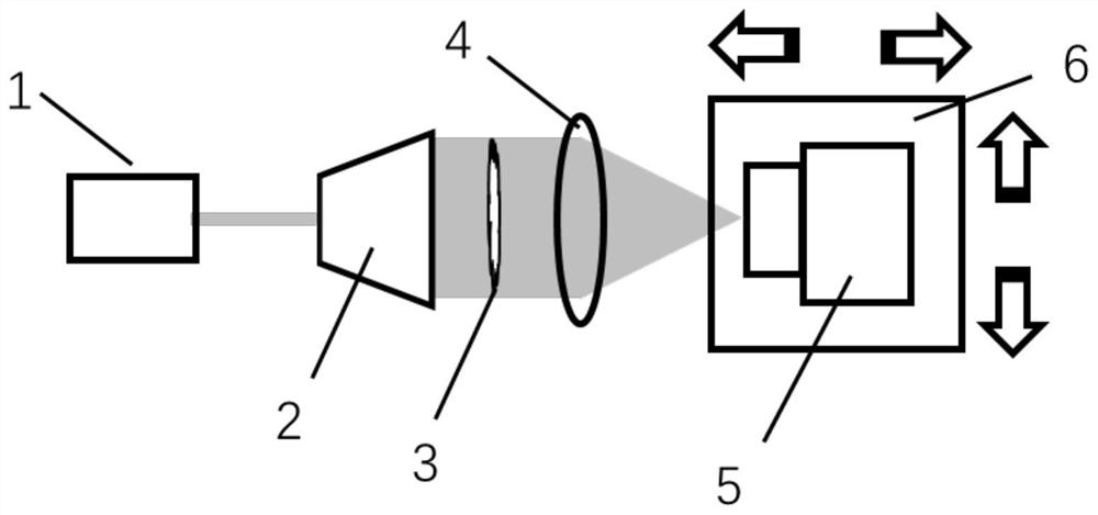
[0043] Such as Figure 1~3 As shown, in the wavefront detection method based on cross iterative autofocus of the present invention, a beam expander 2, a flat panel to be measured 3, a converging lens 4, and an image sensor 5 are sequentially arranged on the outgoing optical path of the laser 1, and the method includes the following steps :

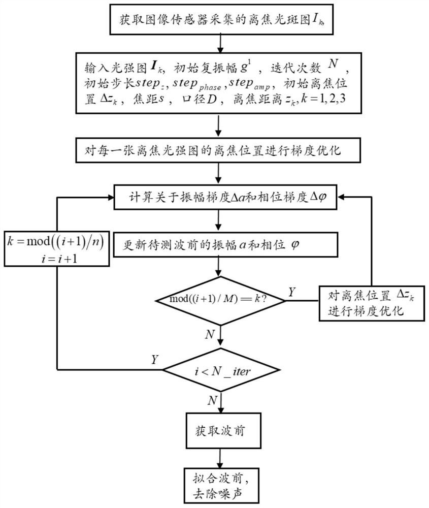
[0044] S1: move the image sensor 5 to collect n defocused spots containing the wavefront error of the plate to be measured at different defocus distances;

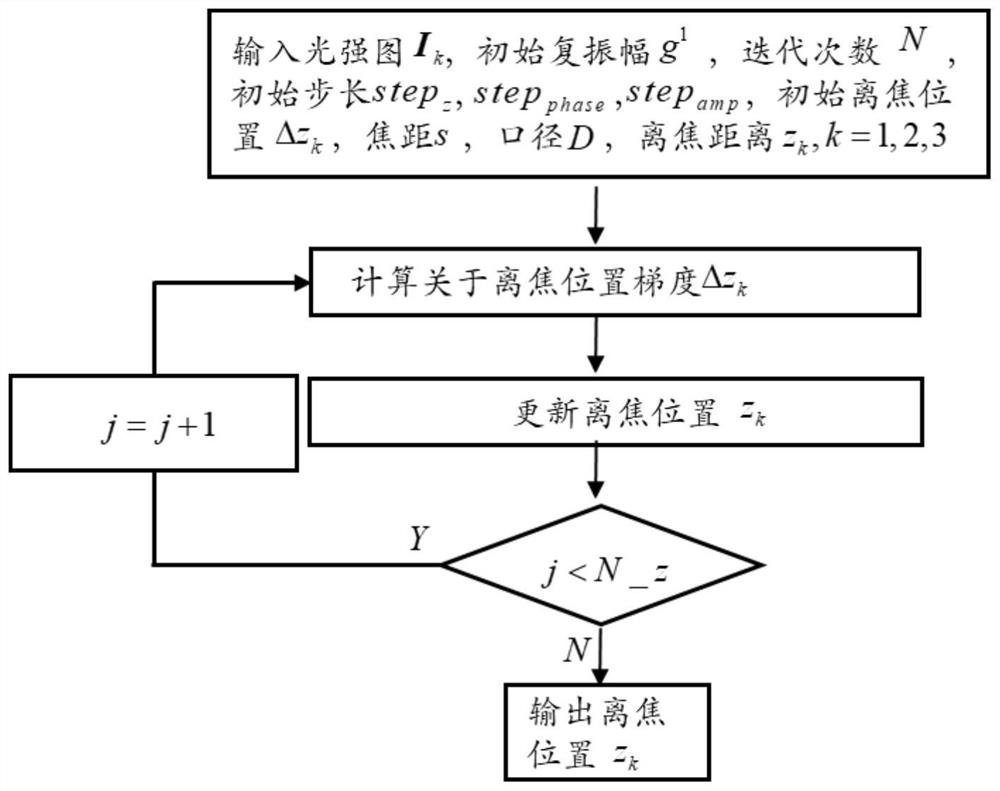
[0045] S2: Set the focal length s of the converging lens, the aperture D, and the nominal defocus position z of...


PUM


Abstract

The invention discloses a wavefront detection method based on cross iterative automatic focusing. The method uses the analytical gradient formula to optimize the defocus distance to realize the automatic determination of the defocus position, and uses the cross iteration method to overcome the inaccurate determination of the defocus position caused by the inaccuracy of the wavefront and the inaccurate determination of the defocus position caused by the uncertainty of the defocus position. For the problem of inaccurate wavefront reconstruction, by optimizing the defocus distance, wavefront amplitude and phase for the same objective function, the accurate reconstruction of defocus position and wavefront error is realized. The invention realizes accurate determination of large defocus errors of multiple images, and realizes accurate reconstruction of wavefront under the condition of uncertain defocus positions without additional construction of an objective function.

Description

technical field [0001] The invention relates to the technical field of optical measurement and imaging, in particular to a wavefront detection method based on cross iterative autofocus. Background technique [0002] Computational imaging has greatly changed the WYSIWYG model of traditional imaging. Through computer post-processing, it overcomes the imperfect imaging of traditional imaging systems and reduces the size and weight of imaging systems. Coherent diffraction imaging is an implementation of computational imaging. Coherent diffraction imaging is a quantitative phase imaging method based on an iterative method; the image sensor is used to collect diffraction images on the focal plane or the defocused plane; the amplitude of the wavefront or image to be measured is obtained by repeated iterative calculations using Fourier transform and inverse Fourier transform and phase; the processing of the amplitude or support domain in the iterative process is similar to mapping ...

Claims


Application Information

Patent Timeline
Patent Type & Authority Patents(China)
IPC IPC(8): G01J9/00
CPCG01J9/00G01J2009/002
Inventor 白剑赵磊汪凯巍侯晶
Owner ZHEJIANG UNIV
Why Eureka
Try Eureka