
Semi-automatic rotor magnetic steel pasting device

A semi-automatic, magnetic steel technology, applied in electromechanical devices, manufacturing stator/rotor bodies, electric components, etc., can solve problems such as low production efficiency, short production cycle, and inability to guarantee product consistency, and achieve easy operation and low cost. , to ensure the effect of production consistency

Pending Publication Date: 2021-06-04
WUXI XINJIE ELECTRICAL
View PDF0 Cites 2 Cited by
  • Summary
  • Abstract
  • Description
  • Claims
  • Application Information

AI Technical Summary

Problems solved by technology

[0002] With the development of social economy, the production cycle of products is required to be shorter and shorter. At present, the rotor magnetic steel station is manually completed. Not only the production efficiency is low, but also the consistency of the product cannot be guaranteed. It is necessary to design a Equipment can greatly improve product production efficiency and product consistency

Method used


Image

  • Semi-automatic rotor magnetic steel pasting device
  • Semi-automatic rotor magnetic steel pasting device
  • Semi-automatic rotor magnetic steel pasting device

Examples


Embodiment Construction

[0022] The present invention will be described in detail below in conjunction with the implementations shown in the drawings, but it should be noted that these implementations are not limitations of the present invention, and those of ordinary skill in the art based on the functions, methods, or structural changes made by these implementations Equivalent transformations or substitutions all fall within the protection scope of the present invention.

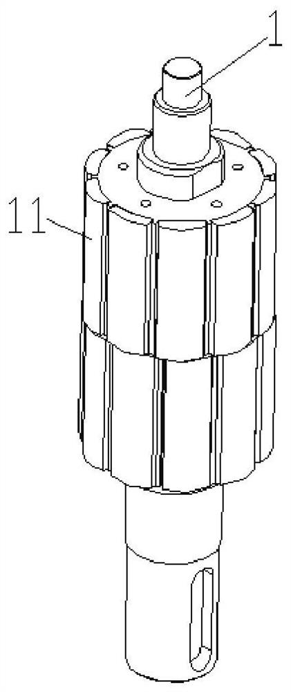
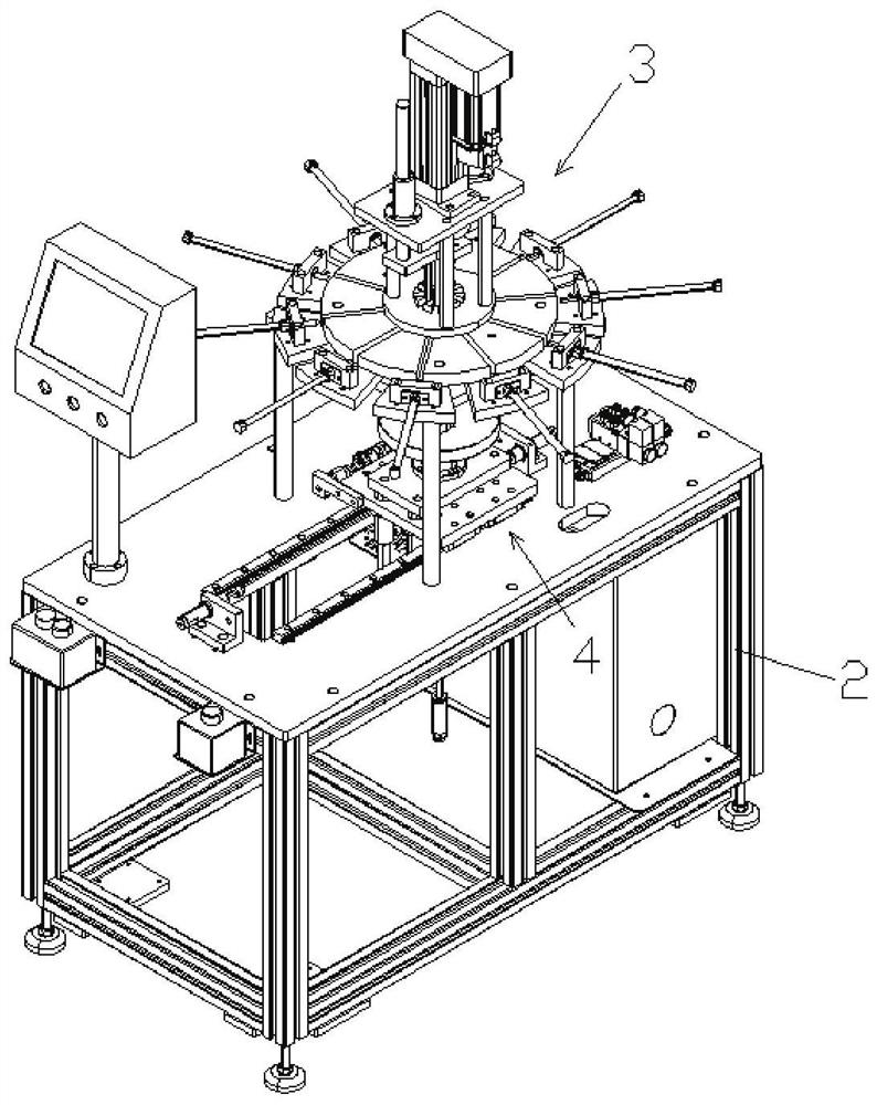
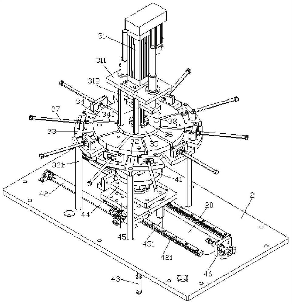
[0023] Such as Figure 1-7 The shown semi-automatic rotor magnetic steel attachment device includes a frame 2, a magnetic steel storage positioning mechanism 3 and a rotor positioning error prevention mechanism 4 installed on the frame 2 and arranged up and down.

[0024] The magnetic steel storage positioning mechanism 3 includes a magnetic steel storage positioning tool, ten magnetic steel cylinders 37 for pushing away, an electric cylinder 31, a magnetic steel separation push block 38 connected to the electric cylinders 31, and...


PUM


Abstract

The invention provides a semi-automatic rotor magnetic steel pasting device. The semi-automatic rotor magnetic steel pasting device comprises a rack, a magnetic steel storage positioning mechanism and a rotor positioning mistake-proofing mechanism, wherein the magnetic steel storage positioning mechanism and the rotor positioning mistake-proofing mechanism are installed on the rack and arranged up and down; the magnetic steel storage positioning mechanism comprises a magnetic steel storage positioning tool, a plurality of magnetic steel pushing air cylinders, an electric cylinder, a magnetic steel separating pushing block connected with the electric cylinder and a magnetic steel positioning shaft. A through hole is formed in the middle of the magnetic steel storage positioning tool, a plurality of guide grooves for placing magnetic steel are formed in the magnetic steel storage positioning tool, the guide grooves are communicated with the through hole, the magnetic steel pushing air cylinders are aligned to inlets of the guide grooves, the magnetic steel separating pushing block is located between the magnetic steel positioning shaft and outlets of the guide grooves, and the bottom of the magnetic steel separating pushing block abuts against the magnetic steel. The semi-automatic rotor magnetic steel pasting device is simple in structure, easy to operate and low in cost, ten pieces of magnetic steel can be attached to a rotor at the same time, the production efficiency of rotor magnetic steel pasting is improved, the labor intensity of workers is reduced, and the production consistency of products is guaranteed.

Description

technical field [0001] The invention relates to the technical field of rotor magnetic steel attachment, in particular to a semi-automatic rotor magnetic steel attachment device. Background technique [0002] With the development of social economy, the production cycle of products is required to be shorter and shorter. At present, the rotor magnetic steel station is manually completed, which not only has low production efficiency, but also cannot guarantee the consistency of products. It is necessary to design a Equipment can greatly improve product production efficiency and product consistency. Contents of the invention [0003] The purpose of the present invention is to disclose a semi-automatic rotor magnetic steel attachment device, which has a simple structure, is easy to operate, and has low cost. Ten pieces of magnetic steel can be attached to the rotor at the same time, which improves the production efficiency of the rotor magnetic steel attachment and reduces the l...

Claims


Application Information

Patent Timeline
Patent Type & Authority Applications(China)
IPC IPC(8): H02K15/03
CPCH02K15/03
Inventor 杨春明徐培曦
Owner WUXI XINJIE ELECTRICAL
Learn More