Supercharge Your Innovation With Domain-Expert AI Agents!

Efficient membrane separation dust removal equipment

A technology of dust removal equipment and high-efficiency membrane, which is applied in the field of membrane separation equipment, and can solve problems such as clogging, attachment to the end face of the microfiltration membrane, accumulation, etc.

Active Publication Date: 2021-06-08
湖北恒德贾隆塑业有限公司
View PDF4 Cites 0 Cited by
  • Summary
  • Abstract
  • Description
  • Claims
  • Application Information

AI Technical Summary

Problems solved by technology

[0003] Based on the inventor's discovery above, the existing high-efficiency membrane separation dedusting equipment mainly has the following shortcomings, for example: because the waste gas is produced by incineration, there will be a certain amount of steam mixed in the waste gas, and the steam will be in contact with the dedusting equipment When it encounters condensation, it will condense into small water droplets. When the small water droplets are mixed with dust, a small mud mass will be formed and attached to the end face of the microfiltration membrane. When the mud mass solidifies, it will block the filter pores of the microfiltration membrane. , resulting in the accumulation of exhaust gas in the dust removal equipment

Method used


Image

  • Efficient membrane separation dust removal equipment
  • Efficient membrane separation dust removal equipment
  • Efficient membrane separation dust removal equipment

Examples


Embodiment 1

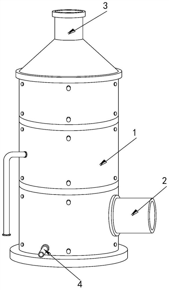
[0026] Example 1: Please refer to Figure 1-Figure 5 , the specific embodiments of the present invention are as follows:

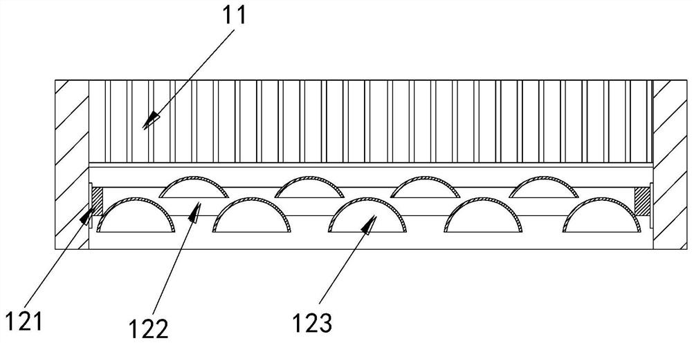
[0027] Its structure includes a main body 1, an air inlet 2, an air outlet 3, and a water outlet 4. The side end of the main body 1 is provided with an air inlet 2, and the air outlet 3 is located in the middle of the top of the main body 1. The drain port 4 is connected to the bottom of the side end of the main body 1. The main body 1 includes a microfiltration membrane 11, a water attachment device 12, a spray device 13, and a separation plate 14. The microfiltration membrane 11 is arranged on the inner top of the main body 1. The water attachment device 12 is located directly below the microfiltration membrane 11 , the spray device 13 is installed at the center of the main body 1 , and the isolation plate 14 is conical and installed at the inner bottom of the main body 1 .

[0028] The water attachment device 12 includes a support plate 121, an install...

Embodiment 2

[0032] Example 2: Please refer to Figure 6-Figure 8 , the specific embodiments of the present invention are as follows:

[0033] The water guide block a1 includes a water guide body b1, a downstream block b2, and a water guide piece b3, the water guide body b1 is in the shape of an arc, and more than eight downstream blocks b2 are arranged, and surround the inner end of the water guide body b1 Arranged, the water guide piece b3 is provided with two, and is respectively located at the inner two ends of the water guide body b1. The guide is directed downward, so that the water can drip from the water guide b1 as soon as possible.

[0034]The water deflector b3 includes a deflector b31, a water flow tank b32, an attached water tank b33, a partition b34, and a sponge pad b34. The upper end of the water guide b31 is provided with a water flow groove b32, and the water flow groove b32 is an arc shape, the attached water tank b33 is located at the bottom end of the baffle b31, the...


PUM


Abstract

The invention discloses efficient membrane separation dust removal equipment, which structurally comprises a main body, an air inlet, an air outlet and a water outlet, the air inlet is formed in the side end of the main body, the air outlet is located in the middle of the top of the main body, and the water outlet is connected to the bottom of the side end of the main body. The main body comprises a micro-filtration membrane, a water adsorption device, a spraying device, and an isolation plate. The water adsorption device comprises a supporting plate, a mounting groove and water guide devices, the water guide device comprises a water guide block, a fixing block, a water guide groove and a water isolation block, and the water isolation block comprises a drainage groove, a clamping groove, a rotating shaft, a water collection piece and a rewinding spring. The water guide devices in the water adsorption device are arranged in a staggered mode two-by-two, thus air flow can wind around the water guide devices, the water mixed in the air flow is attached to the water guide devices, and the water mixed in the air is prevented from being in contact with the dust to be condensed into mud on the end surface of the micro-filtration membrane.

Description

technical field [0001] The invention relates to the field of membrane separation equipment, in particular to a high-efficiency membrane separation and dedusting equipment. Background technique [0002] In the development of modern industry, the exhaust gas produced has always been the main factor that pollutes the environment. The exhaust gas discharged into the air contains not only harmful gases, but also a large amount of dust. Usually, it will be purified after being discharged into the air to avoid environmental pollution. Larger pollution, when purifying the dust mixed in the exhaust gas, it is necessary to use a microfiltration membrane to purify the dust in the exhaust gas. [0003] Based on the inventor's discovery above, the existing high-efficiency membrane separation dedusting equipment mainly has the following shortcomings, for example: because the waste gas is produced by incineration, there will be a certain amount of steam mixed in the waste gas, and the stea...

Claims


Application Information

Patent Timeline
Patent Type & Authority Applications(China)
IPC IPC(8): B01D50/00B01D46/54B01D47/06
CPCB01D46/543B01D47/06B01D50/60
Inventor 周倩芸
Owner 湖北恒德贾隆塑业有限公司
Features
  • R&D
  • Intellectual Property
  • Life Sciences
  • Materials
  • Tech Scout
  • Unparalleled Data Quality
  • Higher Quality Content
  • 60% Fewer Hallucinations
Learn More