Metal cutting machine tool with quick response secondary clamping function

A fast-response, metal cutting technology, used in metal processing mechanical parts, metal processing equipment, clamping and other directions, can solve the problems of incomplete clamping, long clamping stroke, slow clamping speed, etc., to improve the extrusion strength , The effect of short clamping stroke and fast clamping

Inactive Publication Date: 2021-06-08
陈首君
View PDF6 Cites 4 Cited by
  • Summary
  • Abstract
  • Description
  • Claims
  • Application Information

AI Technical Summary

Problems solved by technology

[0002] Metal cutting is usually processed on a cutting machine tool. During cutting, the workpiece material with a columnar structure is inserted into the chuck, and then the chuck is controlled to move centripetally and clamp the workpiece. At present, the above clamping parts have slow clamping speed and long clamping stroke; Moreover, there is no pre-tightening function, resulting in low clamping force and prone to incomplete clamping; the other three clamping parts will have asynchronous displacement after a period of use, that is to say, it will affect the clamping force after multiple clamping. The coaxiality of the workpiece processing, and does not have the function of synchronous adjustment

Method used


Image

  • Metal cutting machine tool with quick response secondary clamping function
  • Metal cutting machine tool with quick response secondary clamping function
  • Metal cutting machine tool with quick response secondary clamping function

Examples


Embodiment 1

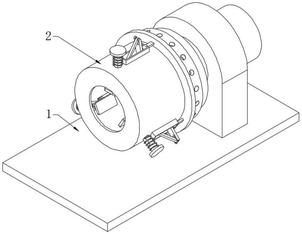
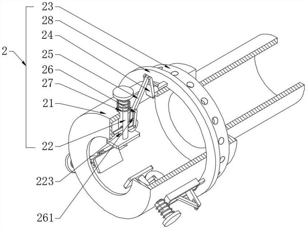
[0032] see Figure 1-3 , a metal cutting machine tool with quick-response secondary clamping function, including a workbench 1 and a clamping mechanism 2 arranged on the workbench 1, the clamping mechanism 2 is used to clamp and fix shaft-like workpieces, its When rotating at high speed, the external cutting tool can be fed to cut and process the workpiece; the clamping mechanism 2 includes a positioning sleeve 21, a clamping rod 22, a driving sleeve 23, a transmission rod one 24, a transmission rod two 25, a pressure rod 26, and a return spring 27 and the pressure ring 28, the positioning sleeve 21 and the workbench 1 rotate and cooperate. The outer wall of the positioning sleeve 21 is provided with three guide holes 211 evenly distributed in the circumferential direction. The clamping rod 22 is sleeved in the guide hole 211 and is axially elastic. Sliding fit, specifically, the other end of the clamping rod 22 is fixedly provided with a limiting disc 222, the return spring 2...

Embodiment 2

[0034] see Figure 4 and Figure 5, and the difference from Embodiment 1 is that a limit disc 21211 is fixedly installed on the limit plate 2121 and the rotation connection of the pressure rod 26, and the limit disc 21211 engages with the outer periphery of the pressure roller 3, and the pressure roller 3 and the limit circle The discs 21, 211 can all be made into a gear structure. The roller shaft of the pressure roller 3 is fixedly sleeved with an eccentric disc 31 that rolls and fits with the pressure plate 221. When the pressure rod 26 swings to the axial direction of the positioning sleeve 21, the pressure roller 3 will rotate. Furthermore, the eccentric disk 31 will follow the rotation, so that the stroke of the pressing rod 26 and the extrusion stroke of the eccentric disk 31 can increase the extrusion force on the pressing plate 221 and improve the extrusion strength. The outer sleeve of the eccentric disk 31 is provided with Rolling circle 311.

Embodiment 3

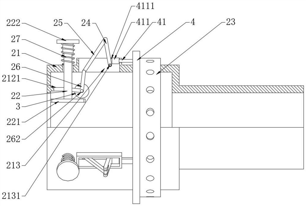
[0036] see image 3 The difference from Embodiment 1 is that one end of the push rod 41 is screwed with an adjustment sleeve 411, so that when the three pressure plates 221 are not equal to the axis of the positioning sleeve 21, it can be adjusted by rotating a single adjustment sleeve 411, which has centering adjustment Function, one end of the adjustment sleeve 411 is provided with a ball 4111 used in conjunction with one side of the transmission rod one 24 .

[0037] Working principle: When in use, the driving sleeve 23 is controlled to rotate, and the driving sleeve 23 moves backward along the axial direction of the positioning sleeve 21. Under the action of the return spring 27, the clamping rod 22 slides outward. At this time, the three pressure plates 221 Insert the shaft-like workpiece from one end of the positioning sleeve 21, and then control the driving sleeve 23 to rotate in reverse, which pushes the transmission ring 4 to slide on the positioning sleeve 21, and th...


PUM


Abstract

The invention discloses a metal cutting machine tool with a quick response secondary clamping function. The metal cutting machine tool comprises a workbench and a clamping mechanism arranged on the workbench, the clamping mechanism comprises a positioning sleeve, a clamping rod, a driving sleeve, a transmission rod I, a transmission rod II, a pressing rod, a reset spring and a pressing ring, the positioning sleeve is in running fit with the workbench, and three guide holes which are uniformly distributed in the circumferential direction are formed in the outer surface wall of the positioning sleeve. The clamping mechanism is arranged, the clamping mechanism comprises the positioning sleeve, the clamping rod, the driving sleeve, the transmission rod I, the transmission rod II, the pressing rod, the reset spring and the pressing ring, the driving sleeve is controlled to rotate to drive the pressing ring to push the transmission rod I to swing, then the pressing rod is driven to swing through the transmission effect of the transmission rod II, the pressing rod swings to drive the clamping rod to act to achieve clamping or loosening control over a workpiece, and the clamping rod is controlled to clamp the workpiece in a swinging mode, so that clamping is quick, and the clamping stroke is short.

Description

technical field [0001] The invention relates to the technical field of metal cutting machine tools, in particular to a metal cutting machine tool with a fast-response secondary clamping function. Background technique [0002] Metal cutting is usually processed on a cutting machine tool. During cutting, the workpiece material with a columnar structure is inserted into the chuck, and then the chuck is controlled to move centripetally and clamp the workpiece. At present, the above clamping parts have slow clamping speed and long clamping stroke; Moreover, there is no pre-tightening function, resulting in low clamping force and prone to incomplete clamping; the other three clamping parts will have asynchronous displacement after a period of use, that is to say, it will affect the clamping force after multiple clamping. The coaxiality of the workpiece processing, and does not have the function of synchronous adjustment. [0003] Accordingly, the present invention provides a meta...

Claims


Application Information

Patent Timeline
Patent Type & Authority Applications(China)
IPC IPC(8): B23Q3/12
CPCB23Q3/12
Inventor 陈首君
Owner 陈首君
Why Eureka
Try Eureka