Conveying device for electronic product detection
A technology for conveying devices and electronic products, which is applied to conveyor control devices, conveyors, conveyor objects, etc., and can solve problems such as low work efficiency
- Summary
- Abstract
- Description
- Claims
- Application Information
AI Technical Summary
Problems solved by technology
Method used
Image

Examples
Embodiment 1
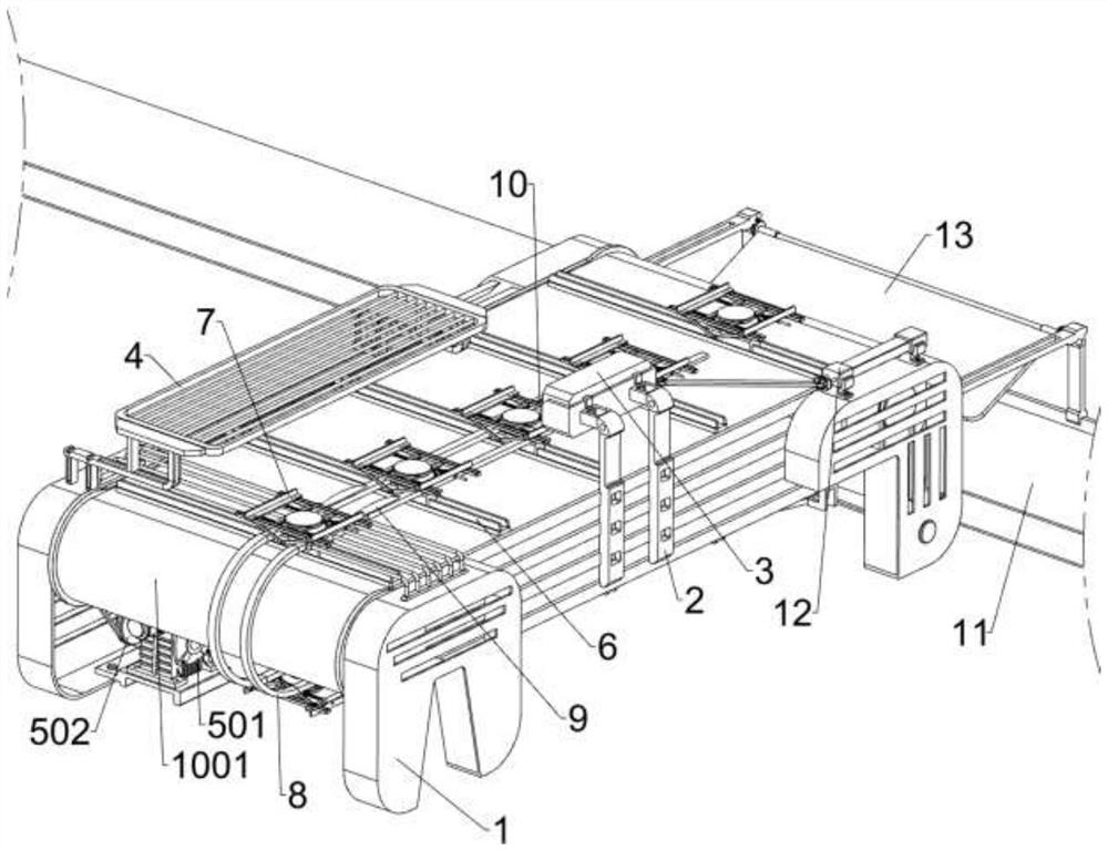
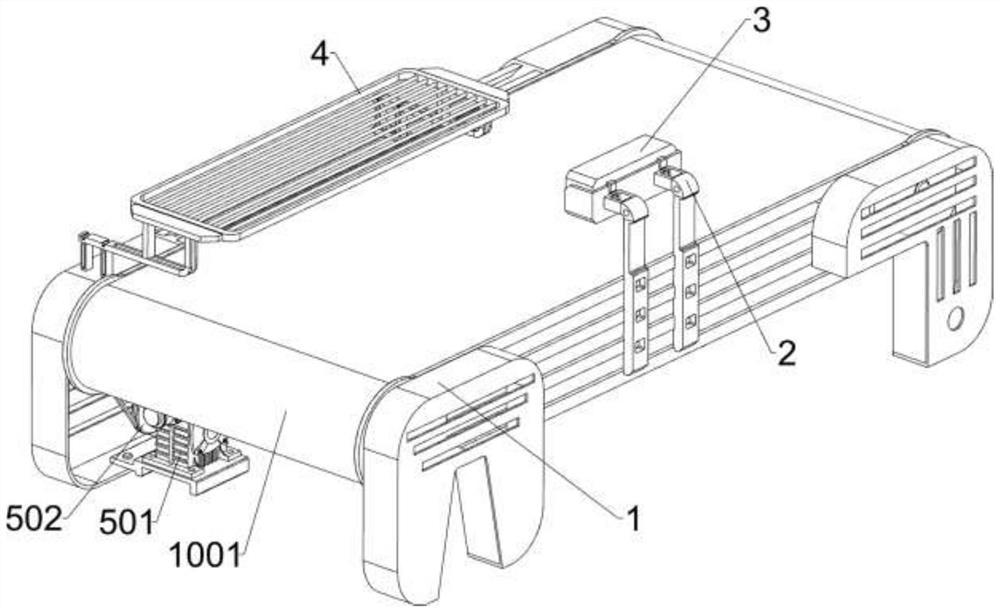
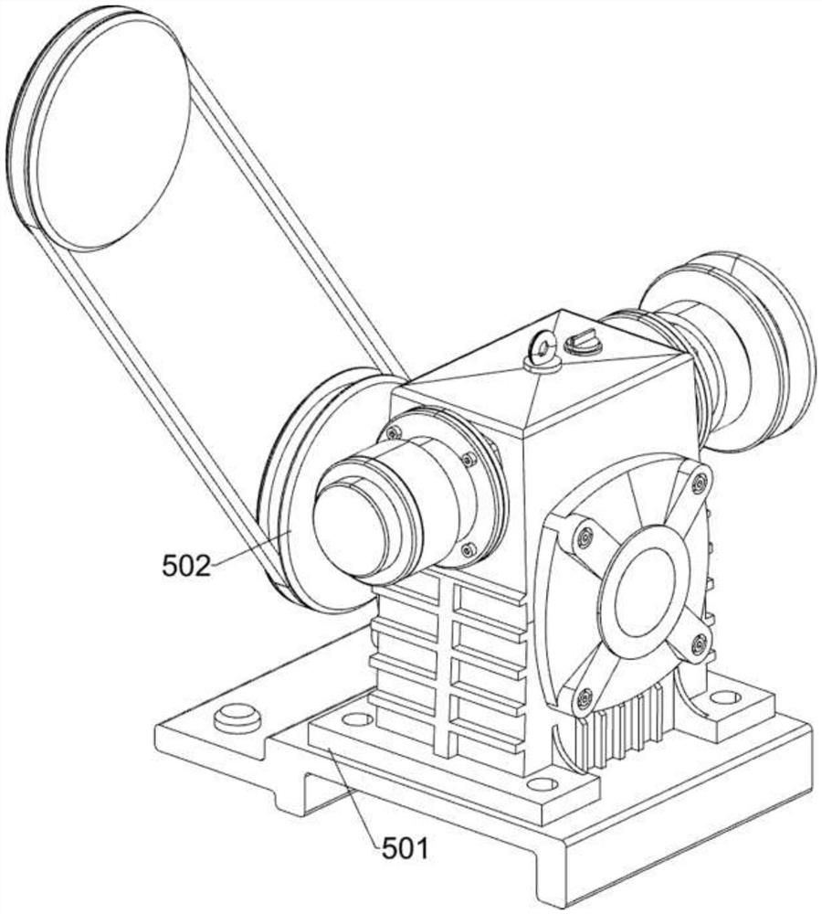
[0033] A conveying device for electronic product inspection, such as Figure 1-5 As shown, it includes a bracket 1, a conveyor belt 1001, a fixed frame 2, a detector 3, a placement plate 4, a power motor 501, a first transmission pulley set 502, a sliding and rotating assembly 6, a fixing assembly 7, and a guiding and reset assembly 8 A conveyor belt 1001 is rotatably arranged on the support 1, and the front side of the support 1 is fixedly connected with a fixed frame 2 by bolts, and a detector 3 is provided on the upper rear side of the fixed frame 2, and a placement plate is provided on the rear upper side of the support 1 4. A power motor 501 is provided on the lower side of the bracket 1, a first transmission pulley set 502 is provided between the output shaft of the power motor 501 and the conveyor belt 1001, and a sliding and rotating assembly 6 is provided on the conveyor belt 1001. The sliding and rotating assembly 6 is provided with a fixing component 7, and the brac...
Embodiment 2
[0042] On the basis of Example 1, such as figure 1 , Figure 6 , Figure 7 , Figure 8 , Figure 9 and Figure 10 As shown, it also includes an automatic release assembly 9, the automatic release assembly 9 includes a swing frame 91 and a projection 92, and the left and right sides of the splint 72 are rotatably connected with a swing frame 91, and the upper side of the special-shaped track 82 All have a bump 92, and the bump 92 cooperates with the swing frame 91.
[0043] When the soft rail 61, the slide block 62, the disc 63 and the turntable 64 move on the conveyor belt 1001, the swing frame 91 will be moved, and then contact with the projection 92, so that the swing frame 91 will move upwards, thereby The splint 72 moves outward, and the ordinary spring 74 is stretched, thereby making it convenient to place the electronic product on the turntable 64, thereby improving the efficiency of manual placement. Restoration drives the splint 72 to move inward, thereby clampin...
PUM
 Abstract
Description
Claims
Application Information
 - R&D
- Intellectual Property
- Life Sciences
- Materials
- Tech Scout
- Unparalleled Data Quality
- Higher Quality Content
- 60% Fewer Hallucinations
Browse by: Latest US Patents, China's latest patents, Technical Efficacy Thesaurus, Application Domain, Technology Topic, Popular Technical Reports.
© 2025 PatSnap. All rights reserved.Legal|Privacy policy|Modern Slavery Act Transparency Statement|Sitemap|About US| Contact US: help@patsnap.com