
Patterned electronic light source device based on anodized aluminum template and its manufacturing method

A technology of anodized aluminum and aluminum oxide templates, applied in the field of electronics, can solve the problems of high cost of masks, limited development and application, and low productivity

Active Publication Date: 2022-04-22
GUILIN UNIVERSITY OF TECHNOLOGY
View PDF5 Cites 0 Cited by
  • Summary
  • Abstract
  • Description
  • Claims
  • Application Information

AI Technical Summary

Problems solved by technology

It has high resolution and does not require a mask. However, the working mode of scanning is doomed to low productivity, which is far from meeting the needs.
The working principle of projection electron beam lithography is similar to that of photolithography. It can expose a large area at the same time and greatly improve productivity. However, the high cost of the mask plate, and problems such as proximity effect and space charge effect limit its development and application.

Method used


Image

  • Patterned electronic light source device based on anodized aluminum template and its manufacturing method
  • Patterned electronic light source device based on anodized aluminum template and its manufacturing method
  • Patterned electronic light source device based on anodized aluminum template and its manufacturing method

Examples


specific Embodiment

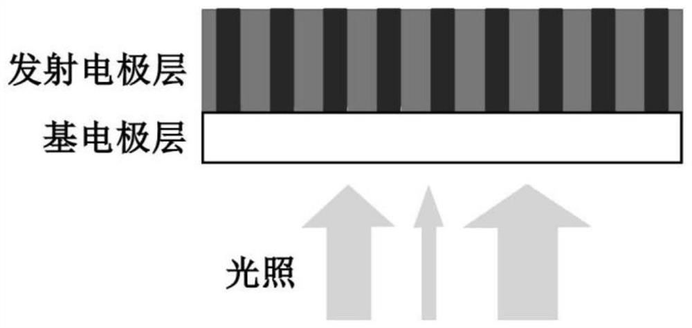
[0043] A patterned electron light source device based on an anodized aluminum template, including two parts: an electron emitter and a light projection irradiation system. The light projection irradiation system adopts the projection system of ordinary light lithography. The cross-sectional view of the electron emitter is shown in figure 1 shown. The emitter consists of two parts: the base electrode layer, which is a transparent conductive layer, and ITO (indium tin oxide) can be used; the emitter electrode layer, the black part is the nano-electrode array for depositing the inner photoelectric effect material, and the white part is the aluminum oxide template skeleton.

[0044] When the light projection irradiation system projects the preset pattern from the back onto the electron emitter, since the emitter contains a nano-electrode array of inner photoelectric effect material, the irradiated nano-electrode will generate photogenerated electrons and holes without The nanoel...


PUM

PropertyMeasurementUnit
diameteraaaaaaaaaa

Abstract

The invention discloses a patterned electronic light source device based on an anodized aluminum template and a manufacturing method thereof, wherein the electronic light source device includes an electron emitter and a light projection irradiation system. The present invention is based on an anodized aluminum template, and fills the inner photoelectric effect material in its nanoholes as a photoelectron emitting nanoelectrode array, and controls the local nanoelectrode to emit electrons by irradiating the nanoelectrode array through light projection; the nanophotoelectrode irradiated by light Photogenerated electrons and holes will be generated, and electrons will be emitted under the action of a negative electric field, while the unirradiated nano-electrode will not emit electrons under the same negative electric field; in this way, the emission of the electron light source device can be changed according to the preset pattern The shape of the electron beam is emitted over a large area. The present invention can conveniently and quickly edit the final electronically projected pattern, that is, the electronic lithography pattern, by changing the light projected pattern.

Description

technical field [0001] The invention relates to the field of electronic technology, in particular to a patterned electronic light source device based on an anodized aluminum template and a manufacturing method thereof. Background technique [0002] Photolithography systems play a vital role in the manufacturing process of semiconductor integrated circuits. As the integration level becomes higher and higher, the size of components becomes smaller and smaller, and the requirements for the resolution of the lithography system are also higher and higher. Utilizing the volatility of electrons, electron beam lithography with electrons as the illumination source can theoretically obtain extremely high resolution. For example, electrons accelerated by 20kV can obtain a wavelength of 0.0086nm. [0003] Electron beam lithography is divided into direct-write electron beam lithography and projection electron beam lithography. Direct-write e-beam lithography works similarly to a scann...

Claims


Application Information

Patent Timeline
Patent Type & Authority Patents(China)
IPC IPC(8): C25D11/12C25D11/20C25D11/24G03F1/78
CPCC25D11/045C25D11/12C25D11/20C25D11/24G03F1/78
Inventor 曹雪丽文剑锋唐涛李明李新宇余静崔丽丹
Owner GUILIN UNIVERSITY OF TECHNOLOGY
Learn More