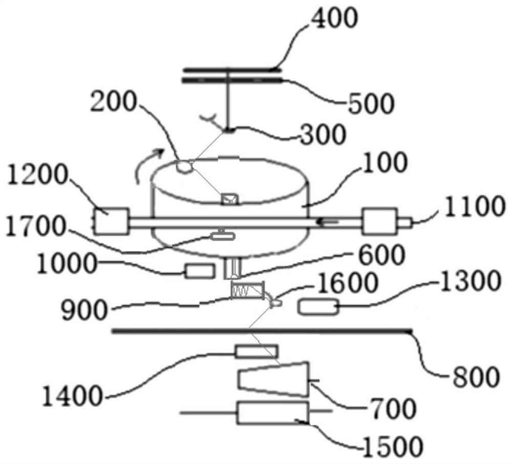
Twisting and winding separation type ring spinning system

A ring spinning, separate technology, applied in the field of spinning, can solve the problems of flying rings, small bobbin capacity, high production cost, etc., and achieve the goals of reducing the height of the balloon, ensuring yarn quality, and reducing friction points Effect

Inactive Publication Date: 2021-06-08
杭州易纱电子商务有限公司
View PDF0 Cites 1 Cited by
  • Summary
  • Abstract
  • Description
  • Claims
  • Application Information

AI Technical Summary

Problems solved by technology

[0004] 1. Restriction of the line speed of the traveler: When the traveler rotates at high speed on the steel ring, it will rub against the steel ring to generate huge heat, which will cause the traveler to heat up sharply and burn out, resulting in flying rings
Therefore, the linear speed of the traveler must be limited within 45m / s, so the spinning speed cannot be further increased
[0005] 2. Constraints on steel ring diameter: limited by factors such as traveler line speed, package power consumption, spinning spindle distance, etc., the maximum steel ring diameter is currently only 45mm, which severely limits the bobbin package capacity and leads to low production efficiency
[0006] 3. Constraints on the running speed of the spindle: Affected by factors such as the structure of the spindle, running stability, power consumption, yarn breakage rate and other factors, the speed of the spinning spindle cannot be further increased at present
[0007] 4. Constraints on the diameter of the balloon: limited by the spindle gauge and winding tension, the diameter of the balloon should not be too large, which restricts the increase in spinning speed
[0008] 5. Restriction of the degree of deterioration of yarn quality by winding: the bobbin capacity is small, there are many joints when winding into a bobbin, and the yarn must be reversed, and the yarn must pass through multiple friction points before being wound into a bobbin. Both seriously deteriorate the yarn quality index
[0009] 6. Restrictions on the production of low-count yarns (such as less than 10 counts): small bobbin capacity, too frequent doffing when producing low-count yarns, extremely low production efficiency, heavy labor, and high production costs. Economical production on ring spinning

Method used


Image

  • Twisting and winding separation type ring spinning system

Examples


Embodiment Construction

[0029] Here, it should be noted that the functions and methods involved in the present invention are merely conventional adaptive applications of the prior art. Therefore, the improvement of the present invention to the prior art lies in the connection relationship between the hardware, rather than the functions and methods themselves. Improve. The description of the functions and methods in the present invention is to better illustrate the present invention so as to better understand the present invention.

[0030] Embodiments of the technical solutions of the present invention will be described in detail below in conjunction with the accompanying drawings. The following examples are only used to illustrate the technical solutions of the present invention more clearly, and therefore are only examples, rather than limiting the protection scope of the present invention.

[0031] It should be noted that, unless otherwise specified, the technical terms or scientific terms used ...


PUM


Abstract

The invention discloses a twisting and winding separation type ring spinning system. The twisting and winding separation type ring spinning system comprises a twisting assembly and a winding assembly; the twisting assembly comprises a horizontally-arranged rotary steel collar, and a steel wire ring detachably installed on the rotary steel collar is arranged on the rotary plane of the rotary steel collar; and the winding assembly comprises a steering gear and a yarn guiding tension roller which are installed in the center of the rotary steel collar. A twisting structure and a winding structure of ring spinning can be separated, the steel collar and a steel wire ring do not become restrictions for improving the spinning speed and the package size any more, and the steering gear can complete the task of assisting winding at the relatively low speed; and the spinning production efficiency can be greatly improved, and the energy consumption per ton of yarn and the raw material consumption can be greatly reduced.

Description

technical field [0001] The invention relates to the technical field of spinning, in particular to a twisting and winding separation type ring spinning system. Background technique [0002] The current ring spinning equipment needs to use the ring spinning frame to produce the bobbin first, and then use the winding machine to unwind the bobbin into a bobbin. The twisting and winding structure of the current ring spinning machine Seriously restricting the increase of production speed. At present, the spindle speed of spinning frame is difficult to break through 20,000rpm, and the yarn needs to be reversed when the bobbin is wound. After the yarn is scraped, the neps and hairiness will increase significantly, and the quality index will seriously deteriorate. . [0003] At present, the ring spinning frame relies on the spindle to drive the bobbin to rotate at high speed, and the yarn drives the traveler to rotate at high speed on the steel ring, thereby completing the twisting ...

Claims


Application Information

Patent Timeline
Patent Type & Authority Applications(China)
IPC IPC(8): D01H1/02D01H1/36D01H13/10
CPCD01H1/02D01H1/36D01H13/108
Inventor 王学元孟进鞠彦军吴永萍
Owner 杭州易纱电子商务有限公司
Why Eureka
Try Eureka