Tire crown structure with heat dissipation function
A tire crown and tire technology, applied in tire parts, reinforcement layers of pneumatic tires, transportation and packaging, etc., can solve the problems of shortening tire service life, declining rubber mechanical properties, and the thickness of tire crown wear-resistant rubber should not be too thick. , to achieve the effect of prolonging the service life, high wear resistance and excellent bearing capacity
- Summary
- Abstract
- Description
- Claims
- Application Information
AI Technical Summary
Problems solved by technology
Method used
Image
Examples
Embodiment 1
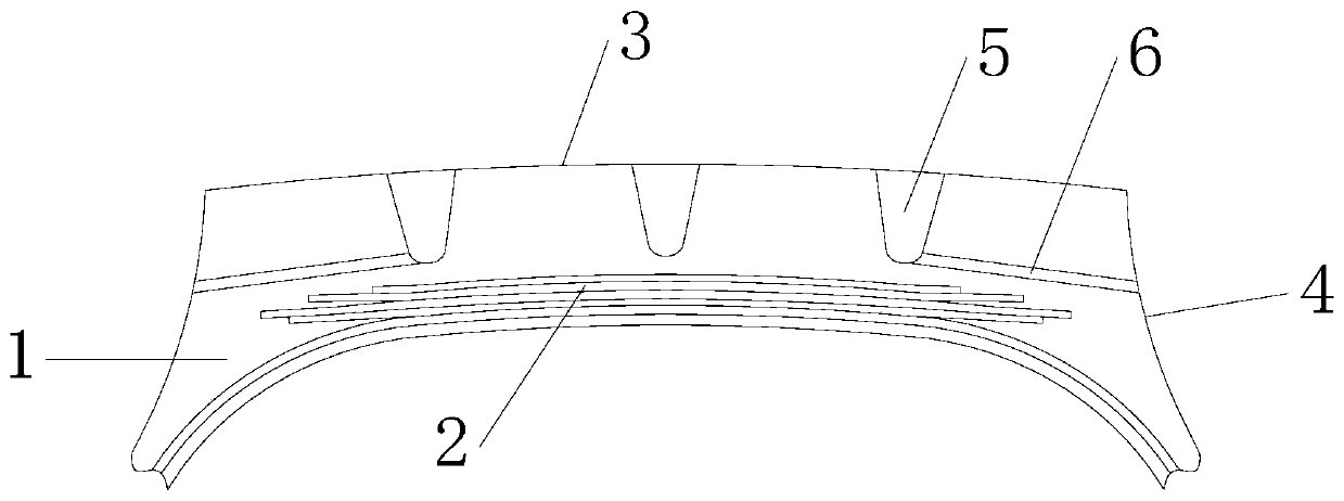
[0024] Example 1, such as figure 1 As shown, the present invention comprises a crown body 1, a tread, and a belt layer 2. The tread can be made of one or more of natural rubber, synthetic rubber, and polyurethane rubber, and is vulcanized by adding rubber fillers and chemical functional additives after mixing. The Shore hardness of the tread is preferably 70HA , which has the advantages of high resilience, tear resistance, and pinning resistance. The tread includes a tire top surface 3 and a tire side surface 4. The tire top surface 3 is provided with pattern grooves 5, and a number of heat dissipation holes are provided in the crown body 1. One or more of 5 are connected, and the heat dissipation holes are located above the belt layer 2. In this embodiment, the heat dissipation holes include a plurality of transverse heat dissipation holes 6, and the transverse heat dissipation holes 6 are arranged along the axial direction, and the included angle between the central axis o...
Embodiment 2
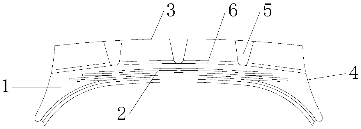
[0025] Example 2, such as figure 2 As shown, the difference between this embodiment and Embodiment 1 is that the crown body 1 is also provided with a plurality of transverse heat dissipation holes 6 in the axial direction between two adjacent pattern grooves 5, and all the transverse heat dissipation holes 6 The radial distances from the central axis of the tire are equal, so that all the transverse cooling holes 6 communicate in circular arcs. The remaining parts are the same as in Embodiment 1 and will not be repeated here.
Embodiment 3
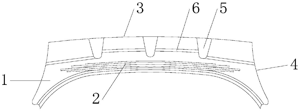
[0026] Example 3, such as image 3 As shown, the difference between this embodiment and embodiment 2 lies in that the radial distance between the transverse cooling holes 6 located between the two pattern grooves 5 and the central axis of the tire is relatively large. The rest are the same as in Embodiment 2, and will not be repeated here.
PUM
 Abstract
Description
Claims
Application Information
 - R&D
- Intellectual Property
- Life Sciences
- Materials
- Tech Scout
- Unparalleled Data Quality
- Higher Quality Content
- 60% Fewer Hallucinations
Browse by: Latest US Patents, China's latest patents, Technical Efficacy Thesaurus, Application Domain, Technology Topic, Popular Technical Reports.
© 2025 PatSnap. All rights reserved.Legal|Privacy policy|Modern Slavery Act Transparency Statement|Sitemap|About US| Contact US: help@patsnap.com


