
Oxygen generation device for air conditioner, air conditioner and control method

The technology of an oxygen generating device and control method is applied in the direction of air conditioning system, heating and ventilation control system, application, etc., and can solve problems such as low work efficiency, decreased oxygen content, and decreased quality of life of users

Pending Publication Date: 2021-06-08
GREE ELECTRIC APPLIANCES INC
View PDF0 Cites 6 Cited by
  • Summary
  • Abstract
  • Description
  • Claims
  • Application Information

AI Technical Summary

Problems solved by technology

In order to ensure the cooling or heating effect of the air conditioner, the user often uses the air conditioner in a closed indoor environment, but the user stays in the closed indoor environment for a long time, which will lead to a decrease in the indoor oxygen content, and lives in an environment with a low oxygen content level for a long time , it will also lead to a decline in the user's quality of life and low work efficiency

Method used


Image

  • Oxygen generation device for air conditioner, air conditioner and control method
  • Oxygen generation device for air conditioner, air conditioner and control method
  • Oxygen generation device for air conditioner, air conditioner and control method

Examples


Embodiment 1

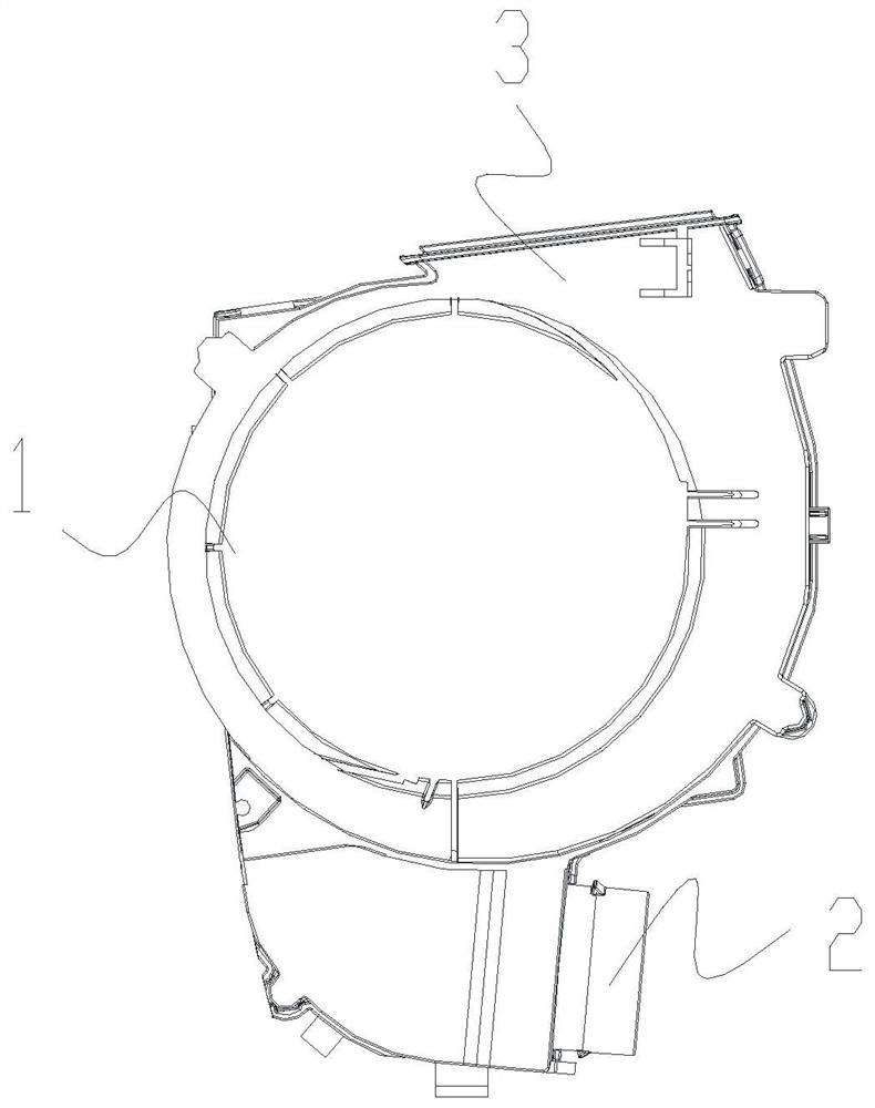
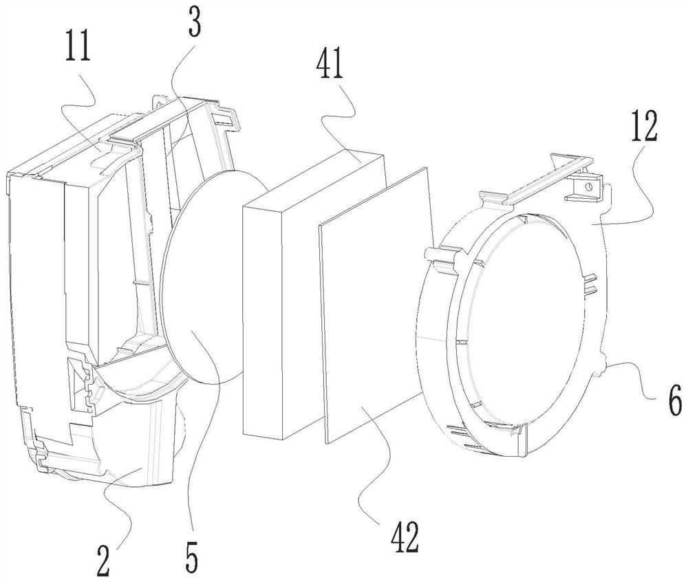
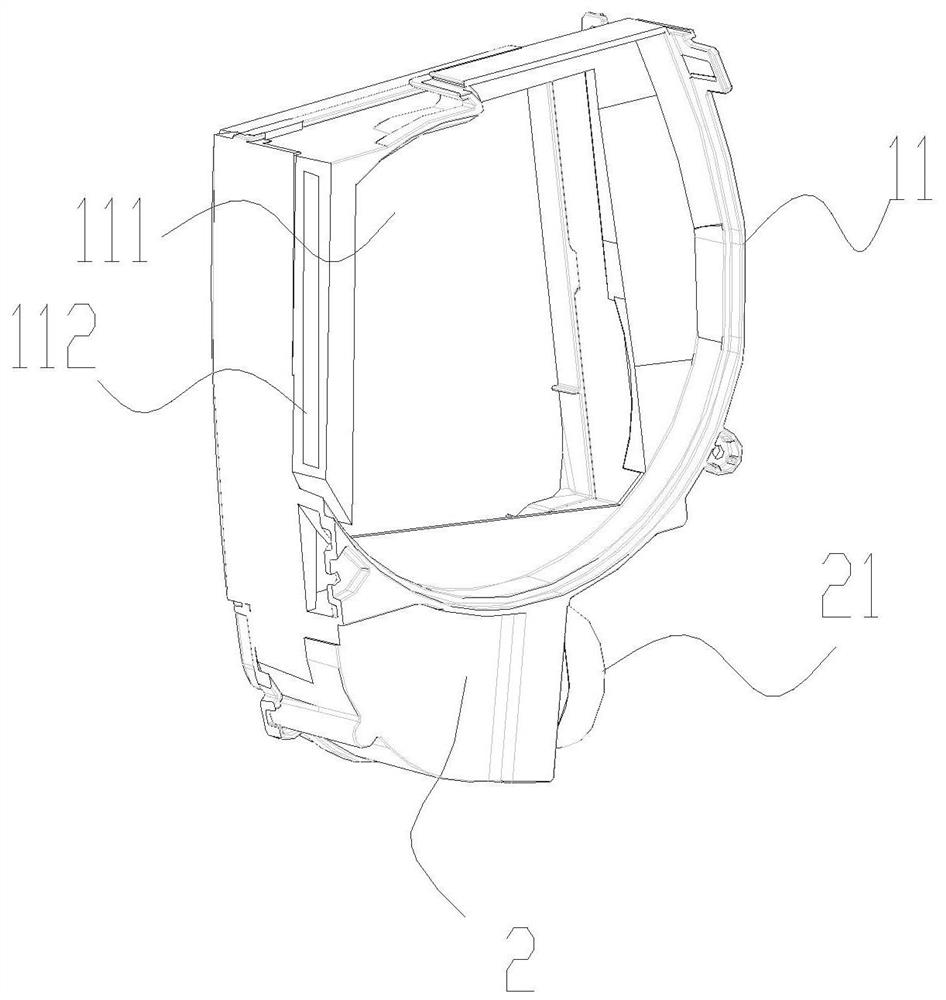
[0038] This embodiment proposes an oxygen generator 200 for an air conditioner, such as Figure 1-4 As shown, it includes a casing 1 and an oxygen generating module inside the casing 1 . A housing chamber 111 is formed in the housing 1, and the housing 1 is provided with an air intake passage 2, a first air outlet passage 3, and a second air outlet passage connected to the housing chamber 111; the oxygen production module is located in the housing chamber 111, and the oxygen production The module includes a sieve type oxygen generator 41 and a molecular sieve 42, the molecular sieve 42 is located in the sieve type oxygen generator 41; when the sieve type oxygen generator 41 is pressurized, when the air entering the accommodation chamber 111 from the air intake channel 2 passes through the molecular sieve 42, the air The nitrogen in the air is adsorbed by the molecular sieve 42, and the oxygen in the air is discharged from the first outlet channel 3 after passing through the mo...

Embodiment 2

[0046] This embodiment also proposes an air conditioner, such as Figure 5 As shown, the air conditioner includes an indoor unit 100, and the indoor unit 100 includes the oxygen generator 200 in Embodiment 1.

[0047] Further optionally, a drain pipe is provided on the indoor unit 100, and the second exhaust channel communicates with the drain pipe. Other unnecessary gases such as water and nitrogen produced by the sieve oxygen generator 41 are discharged outside through the drain pipe.

[0048] Further optionally, an electrical box is provided in the indoor unit 100, and the oxygen generator 200 is arranged close to the electrical box to reduce the wiring distance of the sieve-type oxygen generator 41, and the wiring can be conveniently routed near the electrical box.

[0049] Further optionally, the indoor unit 100 is provided with a fresh air device 300 , and the fresh air device 300 and the oxygen generator 200 are respectively located on two sides of the indoor unit 100 ...


PUM


Abstract

The invention relates to an oxygen generation device for an air conditioner, the air conditioner and a control method. The oxygen generation device comprises a shell and an oxygen generation module, a containing cavity is formed in the device shell, and the device shell is provided with an air inlet channel, a first air outlet channel and a second air outlet channel which are in communication with the device containing cavity; the oxygen generation module is located in the device containing cavity and comprises a screen type oxygen generator and a molecular sieve, and the device molecular sieve is located in the device screen type oxygen generator; when the device screen type oxygen generator is pressurized and air entering the device containing cavity through the device air inlet channel passes through the device molecular sieve, nitrogen in the air is adsorbed by the device molecular sieve, and oxygen in the air passes through the device molecular sieve and then is discharged through the device first air outlet channel; and when the device screen type oxygen generator is decompressed, nitrogen adsorbed on the device molecular sieve and water generated in the pressurization process are discharged through the device second gas outlet channel. The oxygen generation device is installed on the air conditioner to improve the indoor air quality and improve the use experience of a user.

Description

technical field [0001] The invention belongs to the technical field of air conditioners, and in particular relates to an oxygen generator for an air conditioner, an air conditioner and a control method. Background technique [0002] With the gradual improvement of life and users' material level, the user's functional requirements for air conditioners are gradually increasing. In order to ensure the cooling or heating effect of the air conditioner, the user often uses the air conditioner in a closed indoor environment, but the user stays in the closed indoor environment for a long time, which will lead to a decrease in the indoor oxygen content, and lives in an environment with a low oxygen content level for a long time , It will also lead to a decline in the quality of life of users and a state of low work efficiency. [0003] In view of this, the present invention is proposed. Contents of the invention [0004] The technical problem to be solved by the present invention...

Claims


Application Information

Patent Timeline
Patent Type & Authority Applications(China)
IPC IPC(8): F24F1/0071F24F1/0073F24F8/108F24F8/60F24F11/64F24F11/65F24F11/72F24F13/20F24F13/22F24F13/28F24F110/76
CPCF24F3/16F24F13/20F24F13/222F24F13/28F24F11/64F24F11/65F24F11/72F24F2110/76F24F1/0071F24F1/0073Y02B30/70
Inventor 郭强夏光辉王现林安智游俊雄曹端辉
Owner GREE ELECTRIC APPLIANCES INC
Learn More