Underwater hydraulic valve internal and external pressure test system and experiment method
A technology for testing systems and hydraulic systems, applied in the field of testing, can solve the problem that testing equipment cannot truly simulate the working state of underwater hydraulic valves effectively.
- Summary
- Abstract
- Description
- Claims
- Application Information
AI Technical Summary
Problems solved by technology
Method used
Image
Examples
Embodiment approach 1
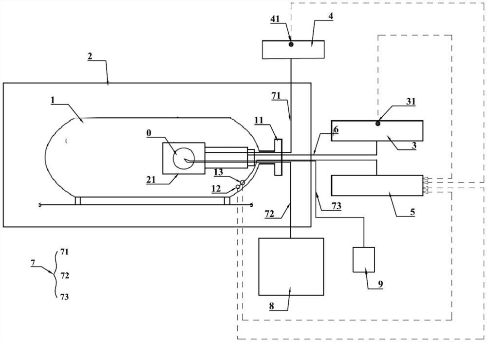
[0030] Implementation mode 1: if figure 1 As shown, the underwater hydraulic valve internal and external pressure testing system includes a hyperbaric chamber 1 for accommodating the hydraulic valve to be tested 0, a sealed chamber temperature control system 2 for providing the hyperbaric chamber 1 with simulated deep-sea ambient temperature conditions, Valve hydraulic system used to control the drive switch of the hydraulic valve O to be tested 3, Valve pressurization system used to apply internal pressure to the hydraulic valve O to be tested 4, Data integration and monitoring for data collection and real-time monitoring for testing System 5, wherein the hyperbaric chamber 1 is placed in the airtight chamber temperature control system 2 as a whole, and the valve hydraulic system 3 is connected to the hydraulic valve 0 to be tested in the hyperbaric chamber 1 through a hydraulic oil pipeline 6. The valve pressurization system 4 is connected to the hydraulic valve 0 to be test...
Embodiment approach 2
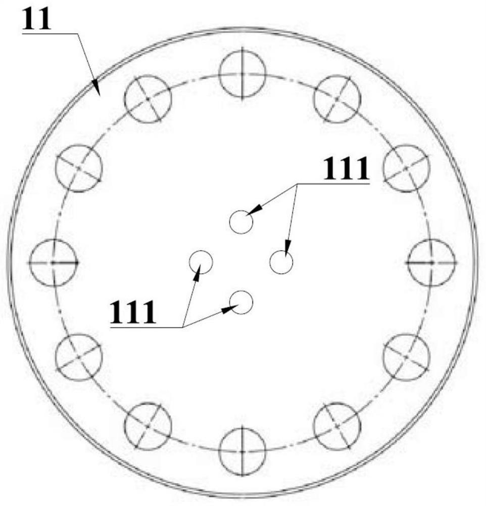
[0031] Implementation mode 2: if figure 2 As shown, in order to realize the opening and closing control of the valve hydraulic system on the hydraulic valve to be tested in the high pressure cabin during the test, the inner end of the hydraulic oil pipeline 6 is connected to the driver of the hydraulic valve to be tested. One end is connected to the valve hydraulic system 3 through the external blind plate 11 of the hyperbaric chamber 1 . The valve hydraulic system can set the hydraulic valve pressurization and pressure release procedures in advance, and complete the opening and closing of the hydraulic valve driver in the high pressure cabin through the hydraulic oil pipeline. The blind plate 11 is provided with a pipe hole 111 for the hydraulic oil pipeline 6 and the high pressure pipeline 7 to be fitted and fixed. The remaining structures and components are as described in Embodiment 1 and will not be described again.
Embodiment approach 3
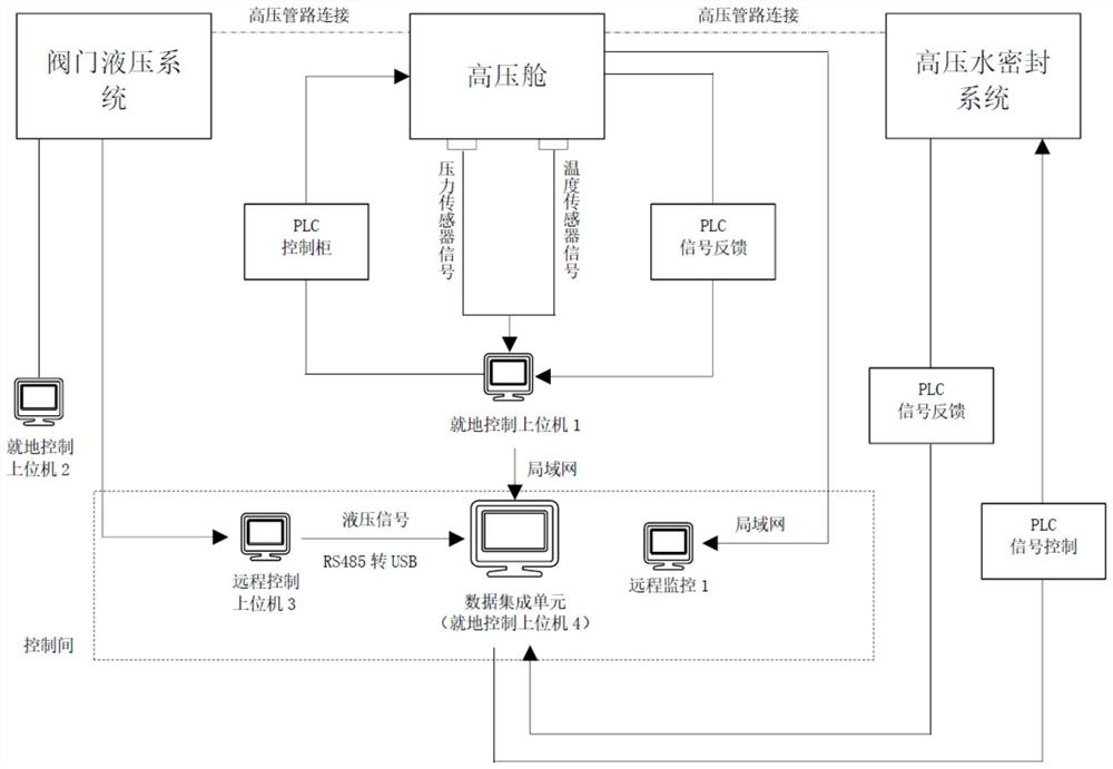
[0032] Implementation mode 3: In order to realize the pressurization and pressure relief of the internal pressure of the hydraulic valve to be tested, during the entire test cycle test, data such as internal and external pressure and temperature can be obtained in real time and the underwater hydraulic valve can be monitored in real time In the test process, the high-pressure pipeline 7 includes a pressurization hose 71, a pressure relief hose 72 and a monitoring leakage pipeline 73, the pressurization hose 71 is connected with the valve pressurization system 4, and the leakage The pressure relief port at the end of the pressure hose 72 is connected to the pressure relief pool 8, and the monitoring leakage pipeline 73 is connected to the beaker 9. The internal and external pressure and the real-time situation in the high-pressure chamber are controlled by the data integration and monitoring system. The high-pressure water sealing system is connected to the upstream and downstre...
PUM
 Abstract
Description
Claims
Application Information
 - R&D
- Intellectual Property
- Life Sciences
- Materials
- Tech Scout
- Unparalleled Data Quality
- Higher Quality Content
- 60% Fewer Hallucinations
Browse by: Latest US Patents, China's latest patents, Technical Efficacy Thesaurus, Application Domain, Technology Topic, Popular Technical Reports.
© 2025 PatSnap. All rights reserved.Legal|Privacy policy|Modern Slavery Act Transparency Statement|Sitemap|About US| Contact US: help@patsnap.com


