Check patentability & draft patents in minutes with Patsnap Eureka AI!

Flow battery stack

A technology for flow batteries and stacks, applied in the field of liquid guide plates, can solve the problems of increasing the thickness and weight of the stack, reducing the mass power density of the stack, and achieving the effect of easy processing

Pending Publication Date: 2021-06-08
DALIAN INST OF CHEM PHYSICS CHINESE ACAD OF SCI
View PDF0 Cites 0 Cited by
  • Summary
  • Abstract
  • Description
  • Claims
  • Application Information

AI Technical Summary

Problems solved by technology

Therefore, the increased liquid guide plate significantly increases the thickness and weight of the stack, and reduces the mass power density of the stack

Method used


Image

  • Flow battery stack
  • Flow battery stack
  • Flow battery stack

Examples


Embodiment

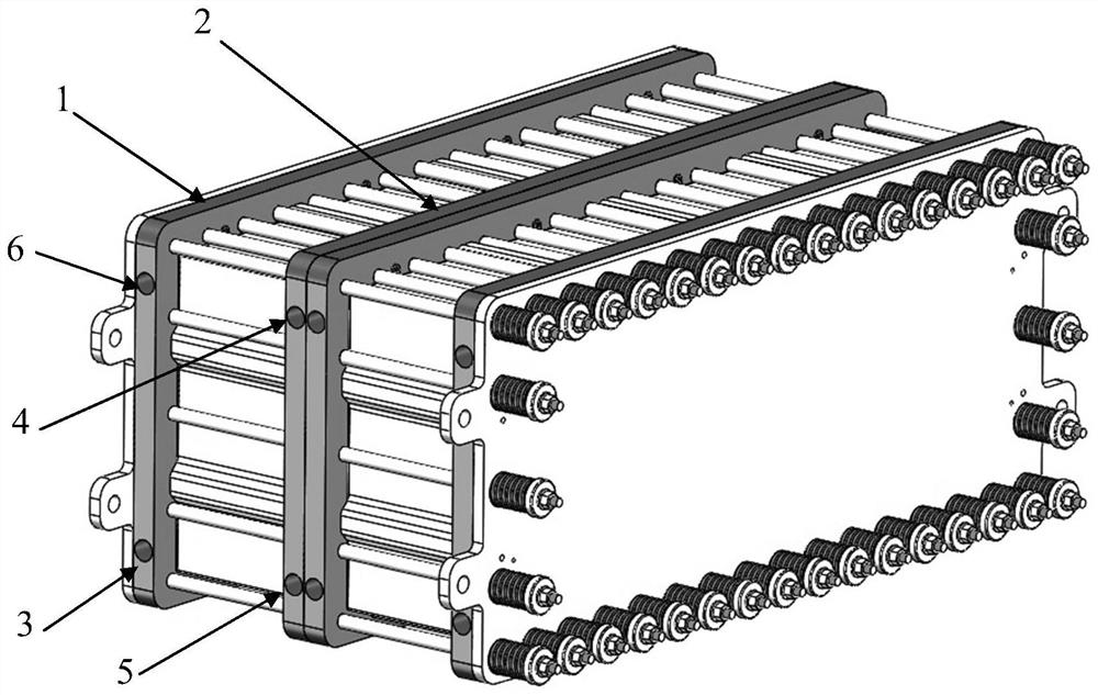
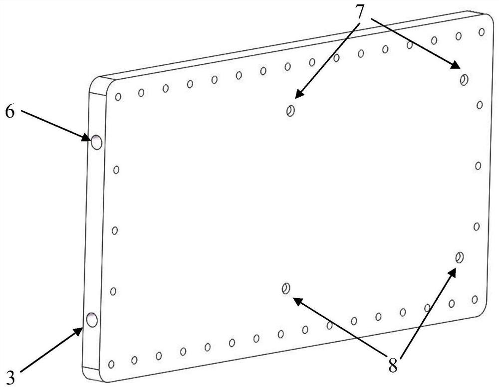
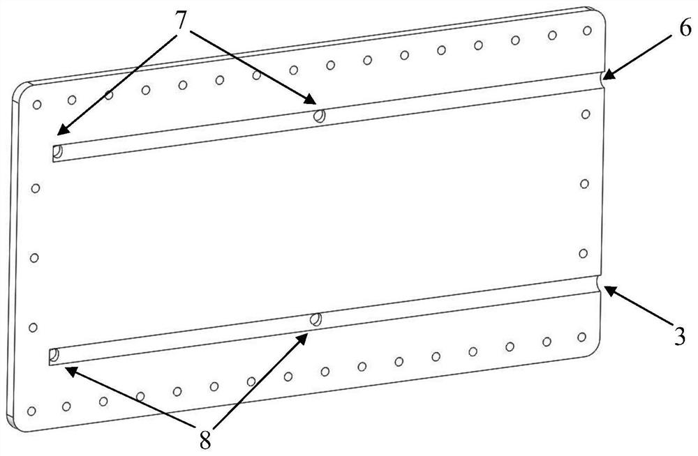
[0023] figure 1 For a conventional liquid flow battery high-power stack, the batteries of the entire stack are divided into two groups, and each group uses a liquid guide plate A ( figure 2 , image 3 ) and guide plate B ( Figure 4 , Figure 5 ) As the positive and negative electrolyte inflow and outflow organizational components. The positive electrode electrolyte flows into the positive electrode of each battery through the positive electrode electrolyte inlet of the 3 liquid guide plate A, and then flows out of the stack through the positive electrode electrolyte outlet of the 4 liquid guide plate B; the negative electrode electrolyte is electrolyzed through the negative electrode of the 5 liquid guide plate B The liquid inlet flows into the negative electrode of each battery, and then flows out of the stack through the negative electrode electrolyte outlet in 6 liquid guide plates A. Among them, the outlet of negative electrode electrolyte in 6 liquid guide plate A i...


PUM

PropertyMeasurementUnit
thicknessaaaaaaaaaa

Abstract

The invention relates to a flow battery stack. The flow battery stack comprises two or more battery packs which are sequentially and alternately connected in series in a manner of a positive electrode end to a negative electrode end, and the positive electrode end and the negative electrode end of the stack are respectively provided with a liquid guide plate; a blind hole serving as a positive or negative electrolyte inlet channel and a blind hole serving as a negative or positive electrolyte outlet channel are respectively formed in the surface of the side edge of the liquid guide plate; and the blind holes are respectively communicated with a positive or negative electrolyte public channel of the battery pack close to the surface of one side of the liquid guide plate. Stack liquid guide plates adopting the structure are large in number and heavy in weight. By adopting the flow battery stack liquid guide plates provided by the invention, two adjacent liquid guide plates between grouped battery packs in the stack are combined into a whole in electrolyte organization function, and the thickness of the liquid guide plate is only equal to that of one liquid guide plate. Therefore, on a 100-kW stack, the number of the liquid guide plates is greatly reduced, and the size of the stack is also obviously reduced.

Description

technical field [0001] The invention relates to a liquid flow battery stack, in particular to a liquid guide plate of a liquid flow battery stack. Background technique [0002] The rapid development of the economy has accelerated the demand for energy, and the excessive exploitation of traditional fossil energy has intensified the pressure on the environment. Therefore, the efficient use of renewable energy has become a priority for the development of energy in various countries. Renewable energy, including wind energy and solar energy, has the problems of discontinuity, instability, and poor adjustability. In order to realize the integration of renewable energy into the grid, it needs to be converted into controllable, stable and continuous power, for which it is necessary to develop intermediate power conditioning equipment. Energy storage technology has emerged as the times require, including physical energy storage and chemical energy storage. Physical energy storage i...

Claims


Application Information

Patent Timeline
Patent Type & Authority Applications(China)
IPC IPC(8): H01M8/0258H01M8/18H01M8/2455
CPCH01M8/0258H01M8/188H01M8/2455Y02E60/50
Inventor 邢枫李先锋张华民
Owner DALIAN INST OF CHEM PHYSICS CHINESE ACAD OF SCI
Features
  • R&D
  • Intellectual Property
  • Life Sciences
  • Materials
  • Tech Scout
  • Unparalleled Data Quality
  • Higher Quality Content
  • 60% Fewer Hallucinations
Learn More