
Water feeding and drainage equipment for aquaculture pond

A technology for aquaculture, water intake and drainage, applied in fish farming, application, animal husbandry, etc., can solve the problems of flushing into the vacuum pressure zone, accumulating into sludge, and reducing the area, so as to achieve great advocacy and benefit Effects of Structural Changes

Inactive Publication Date: 2021-06-11
段幼芬
View PDF7 Cites 0 Cited by
  • Summary
  • Abstract
  • Description
  • Claims
  • Application Information

AI Technical Summary

Problems solved by technology

[0004] Because the excess bait and fish excrement in the water will produce nitrite, when the pump is draining the aquaculture pond, the rotating motion of the impeller will form a vacuum low-pressure area at the center of the impeller shaft blade, which will affect the The water in the culture pond has air pressure adsorption, the water quality is sucked into the diffusion chamber of the pump chamber, and the rotating centrifugal force generated by the impeller throws it out, so that it can be squeezed out from the drain, and when the nitrite is absorbed with the water quality, it is easy Due to the inertial force, it rushes into the vacuum resistance area, and then adheres to the inner ring wall of the low pressure area, accumulating into dirt, resulting in a smaller area of ​​the low pressure area, which reduces the efficiency of water absorption.

Method used


Image

  • Water feeding and drainage equipment for aquaculture pond
  • Water feeding and drainage equipment for aquaculture pond
  • Water feeding and drainage equipment for aquaculture pond

Examples


Embodiment 1

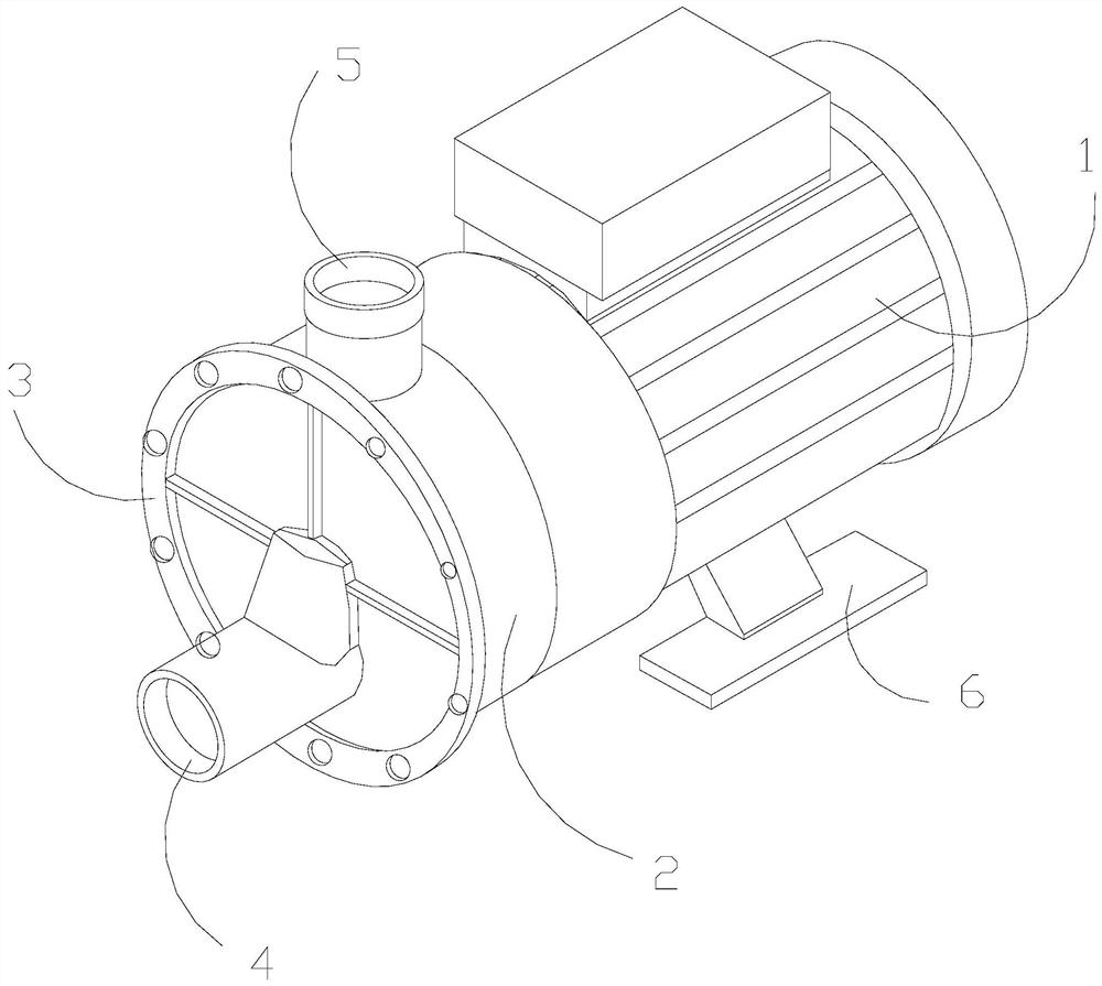
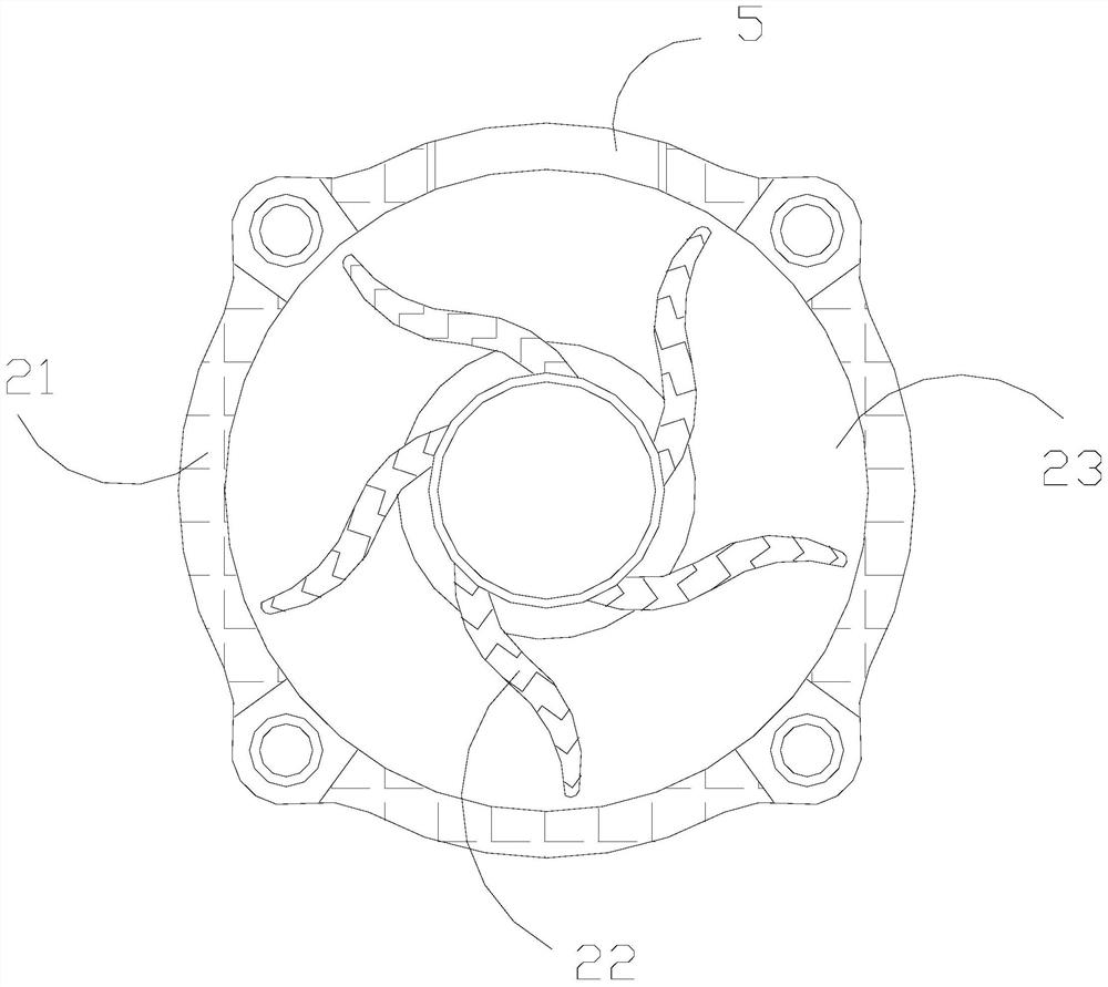
[0029] as attached figure 1 to attach Image 6 Shown:

[0030] The invention provides a water inlet and drainage equipment for aquaculture ponds, the structure of which is provided with a rear drive machine 1, a front suction end 2, a card cover 3, a water inlet 4, a water outlet 5, and a support foot 6, and the support foot 6 is embedded and connected Below the rear drive machine 1, the front suction end 2 is installed at the front end of the rear drive machine 1 and cooperates with it. The card cover 3 is movably engaged with the front end of the front suction end 2. The water inlet 4 and the card cover 3 It is an integrated structure and communicates with each other, and the drain port 5 is connected to the top position of the front suction end 2 .

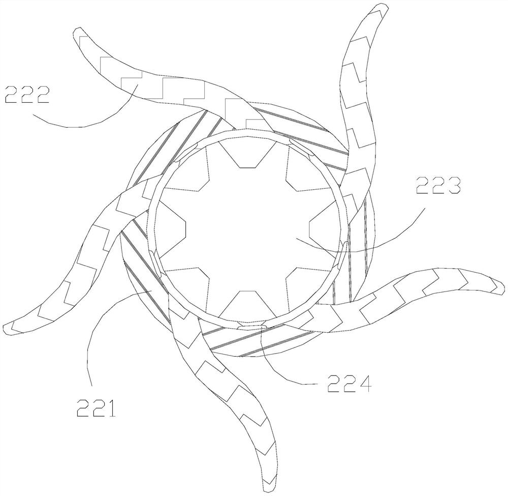
[0031] The front suction end 2 is provided with a frame body 21 , an impeller device 22 , and a water chamber 23 , the water chamber 23 is located at the inner side of the frame body 21 , and the impeller device 22 is embedde...

Embodiment 2

[0038] as attached Figure 7 to attach Figure 8 Shown:

[0039] Wherein, the ring wall block a2 is provided with a side groove rail a21, a front opening a22, an inner cavity a23, an air cushion a24, and an air port a25. The port a22 is located at the front end of the inner cavity a23, the inner cavity a23 and the ring wall block a2 are integrated and located inside, the air cushion a24 is embedded and connected to the rear end of the inner cavity a23, the air port a25 and the air cushion a24 are Integrated structure and through arrangement, the air cushion a24 is in the state of an arc lobe, has excellent elastic force, and can perform ups and downs. Deformation, the front opening a22 has a certain blocking effect on foreign objects, and at the same time generates a blowing force toward the outer end.

[0040] Wherein, the front port a22 is provided with a solid plate c1, an air blowing diameter c2, and a corner block c3, the solid plate c1 and the air blowing diameter c2 ...


PUM


Abstract

The invention discloses water feeding and drainage equipment. The equipment is structurally provided with a rear drive machine, a front suction end, a clamping cover, a water inlet, a water outlet and supporting feet, wherein the supporting feet are fixedly connected to the lower portion of the rear drive machine in an embedded mode, the front suction end is arranged at the front end of the rear drive machine and matched with the rear drive machine, the clamping cover is movably clamped to the front end of the front suction end, the water inlet and the clamping cover are of an integrated structure and communicate with each other, and the water outlet is arranged in the top of the front suction end in a penetrating mode. A movable ring body is integrally of an annular structure, and when centrifugal air pressure acts on the movable ring body, the movable ring body can clamp an annular wall block to move, impurities are contained in an arc pocket shape of a cavity containing channel, a cavity ball is driven by a gravity ball to move up and down, the change of air flow at the end opening of the cavity containing channel is assisted, the absorption of the impurities is facilitated, the impurities enter a carrying cavity through a rear through path in the through opening state, are shaken out again from a front through end under the inertia effect in the annular motion process of the movable ring body and move along with airflow, and therefore the impurities are not prone to being attached to the inner ring wall of an air pressure cavity.

Description

technical field [0001] The invention belongs to the field of drainage, and more specifically relates to a water inlet and drainage device for aquaculture ponds. Background technique [0002] The aquaculture industry is a major industry in my country's economic development. Aquaculture has high requirements for water quality, so it is often necessary to use a pump to replace the water source of the aquaculture pond. The pump can convert its own mechanical energy into liquid energy and form a vacuum at the inlet. Negative pressure state, transporting water from one place to another, is widely used in pumping and drainage operations. [0003] Based on the above-mentioned inventor's discovery, there are following deficiencies in the existing aquaculture pond inlet and drainage equipment: [0004] Because the excess bait and fish excrement in the water will produce nitrite, when the pump is draining the aquaculture pond, the rotating motion of the impeller will form a vacuum low-...

Claims


Application Information

Patent Timeline
Patent Type & Authority Applications(China)
IPC IPC(8): A01K63/04
CPCA01K63/04
Inventor 段幼芬
Owner 段幼芬
Learn More