
Shock wave generating system for cardiovascular stenosis lesion

A system and shock wave generation technology, applied in medical science, surgery, etc., can solve the problems of weakened effect, less function, single pulse parameter setting, etc., and achieve better effect in the treatment of cardiovascular stenosis

Pending Publication Date: 2021-06-11
SUZHOU HUI HEALTHCARE TECH CO LTD
View PDF7 Cites 0 Cited by
  • Summary
  • Abstract
  • Description
  • Claims
  • Application Information

AI Technical Summary

Problems solved by technology

However, the pulse parameter setting in the energy generation controller used in this invention is relatively simple, and it cannot detect and control the energy released by the pulse, and cannot realize the continuous adjustment of the pulse voltage, and releases multiple pulses independently and continuously for severe areas, with few functions. The effect of the system on lesion treatment is weakened

Method used


Image

  • Shock wave generating system for cardiovascular stenosis lesion
  • Shock wave generating system for cardiovascular stenosis lesion
  • Shock wave generating system for cardiovascular stenosis lesion

Examples


Embodiment 1

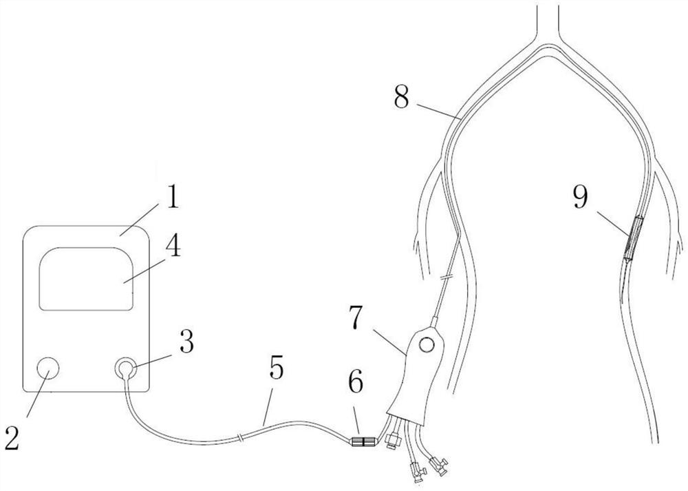
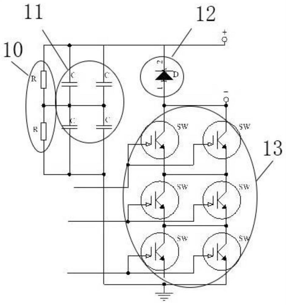
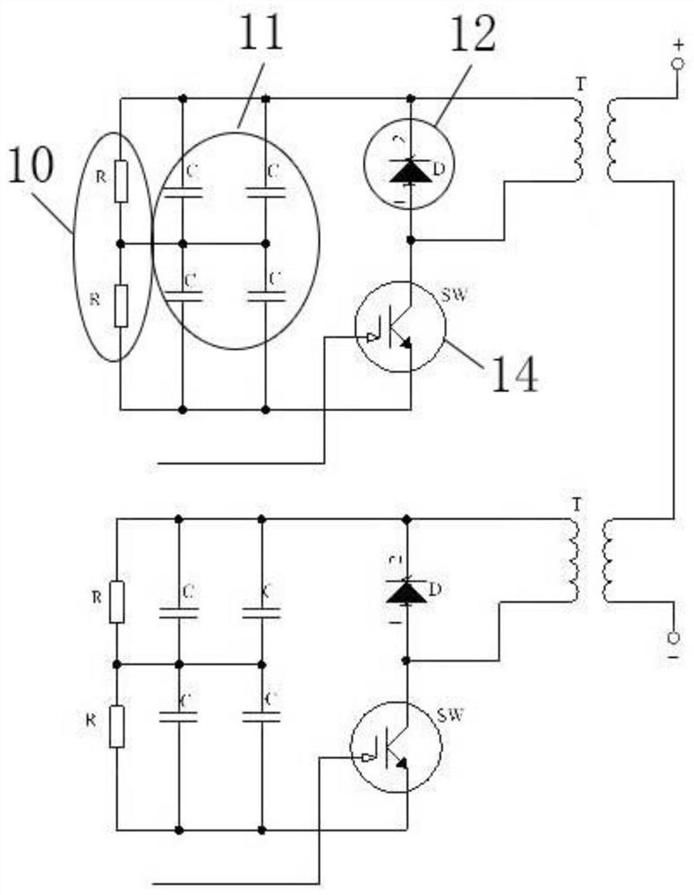
[0047] A high-voltage shock wave generating system for cardiovascular stenosis, the system includes an energy generator 1, the energy generator 1 includes an energy storage device and an energy release control device, and the energy release control device includes a high-voltage pulse circuit, An electrode selection circuit and a release state detection circuit; the high-voltage pulse circuit includes a positive pole, a negative pole, a resistor 10, a capacitor 11, a diode 12 and a switch 13.

[0048] Preferably, the capacitor 11, the diode 12 and the switch 13 are connected in series, the resistor 10 and the capacitor 11 are connected in parallel, and the resistor 10, the capacitor 11, the diode 12 and the switch 13 are divided into one group, and there are M groups in total.

[0049] Preferably, the capacitor 11 includes a single-stage capacitor or a multi-stage capacitor, and the multi-stage capacitor includes one or a combination of multiple capacitors connected in series, ...

Embodiment 2

[0063] This embodiment is carried out on the basis of the above-mentioned embodiment 1, and the similarities with the above-mentioned embodiment will not be repeated.

[0064] This embodiment mainly introduces a principle of a high-voltage pulse circuit.

[0065] A high-voltage pulse circuit comprises a resistor 10, a capacitor 11, a diode 12 and a switch 13; the capacitor 11, the diode 12 and the switch 13 are connected in series, and the resistor 10 is connected in parallel with the capacitor 11; the resistor 10, the capacitor 11, the diode 12 and switches 13 are divided into one group, and there are M groups in total, and M is 1-200.

[0066] Further, by connecting N switches in series as a group, after series voltage division, the voltage division on each switch is one-Nth of the total voltage, which is used to reduce the withstand voltage requirement of each switch, so that the withstand voltage can be used Switches with slightly lower switching speeds achieve fast switc...

Embodiment 3

[0071] This embodiment is described on the basis of the above-mentioned embodiment 2, and the similarities with the above-mentioned embodiment 2 will not be repeated.

[0072] as attached figure 2 As shown, M is 1.

[0073] Further, the resistor 10 is a multi-stage resistor, and the number of the resistors is two.

[0074] Further, the capacitor 11 is a multi-stage capacitor, and the number of the capacitors is four.

[0075] Further, the switch 13 is a multi-level switch, and the number of the switches is six.


PUM


Abstract

The invention relates to a shock wave generation system for cardiovascular stenosis lesion. The system comprises an energy generator, the energy generator comprises an energy storage device and an energy release control device, the energy release control device comprises a high-voltage pulse circuit, an electrode selection circuit and a release state detection circuit; the high-voltage pulse circuit comprises a positive electrode, a negative electrode, a capacitor, a diode, a resistor and a switch. The capacitors, the diodes and the switches are connected in series, the resistors and the capacitors are connected in parallel, the resistors, the capacitors, the diodes and the switches are divided into M groups, and M is a positive integer. According to the invention, the voltage transformation of the pulse circuit can be carried out through the design of the transformer, the capacitor and the switch, so that the pulse voltage can be continuously regulated, the electrode pulse mode can be manually or automatically selected, the continuous pulse number can be controlled, the operation is convenient, quick and efficient, and the lesion treatment effect of the system is better.

Description

technical field [0001] The invention belongs to the technical field of medical equipment, and in particular relates to a shock wave generating system for cardiovascular stenosis. Background technique [0002] Vascular stenosis refers to human arteriovenous vessels, such as coronary arteries, peripheral vessels, and intracranial vessels. Due to abnormal lipid metabolism, lipids in the blood are deposited on the smooth intima of blood vessels, and gradually accumulate into atherosclerotic lipids. Plaque-like plaques, as time goes by, these plaques increase or even calcify, causing narrowing of the blood vessel lumen, blocking blood flow, leading to ischemia of downstream blood vessels and the body, and corresponding clinical manifestations. If the stenosis occurs in the coronary artery, it will cause palpitations, chest pain, dyspnea, and angina pectoris. In severe cases, it will lead to myocardial insufficiency or myocardial necrosis; if it occurs in the periphery, it will ca...

Claims


Application Information

Patent Timeline
IPC IPC(8): A61B17/22
CPCA61B17/22012A61B17/22022A61B2017/22025A61B2017/22051A61B2017/22084A61B2017/22002
Inventor 苗涛程增兵林林
Owner SUZHOU HUI HEALTHCARE TECH CO LTD
Learn More