Supercharge Your Innovation With Domain-Expert AI Agents!

An autonomous combined auxiliary exercise equipment for orthopedic rehabilitation

An exercise equipment, orthopaedic rehabilitation technology, applied in gymnastics equipment, sports accessories, etc., can solve the problems of orthopaedic rehabilitation patients designing training equipment, unable to carry out weight-bearing exercises, and easy to drag trainers.

Active Publication Date: 2022-03-01
WUXI NO 9 PEOPLES HOSPITAL
View PDF6 Cites 0 Cited by
  • Summary
  • Abstract
  • Description
  • Claims
  • Application Information

AI Technical Summary

Problems solved by technology

[0002] Patients with orthopedic diseases need recovery training after treatment. These patients generally have limited limb strength and cannot perform a lot of weight-bearing exercises like ordinary people. Moreover, such trainers are prone to lose their strength, such as training with tension equipment. The pulling force is related to the stretching stroke. As long as there is a stretching stroke, there will be a pulling force. When the trainer is out of force, it is easy to drag the trainer and cause danger.
[0003] In the prior art, there is no training equipment specially designed for orthopedic rehabilitation patients. Generally, common fitness equipment is used, and protective structures are added to prevent falling, etc., while the pulling force is still provided by traditional elastic ropes, etc. There is still a risk factor after detachment, and the patient can only choose less powerful training equipment more safely, and cannot fully stimulate his own strength, but has reservations;

Method used


Image

  • An autonomous combined auxiliary exercise equipment for orthopedic rehabilitation
  • An autonomous combined auxiliary exercise equipment for orthopedic rehabilitation
  • An autonomous combined auxiliary exercise equipment for orthopedic rehabilitation

Examples


Embodiment Construction

[0026] The following will clearly and completely describe the technical solutions in the embodiments of the present invention with reference to the accompanying drawings in the embodiments of the present invention. Obviously, the described embodiments are only some, not all, embodiments of the present invention. Based on the embodiments of the present invention, all other embodiments obtained by persons of ordinary skill in the art without making creative efforts belong to the protection scope of the present invention.

[0027] see Figure 1-6 , the present invention provides technical solutions:

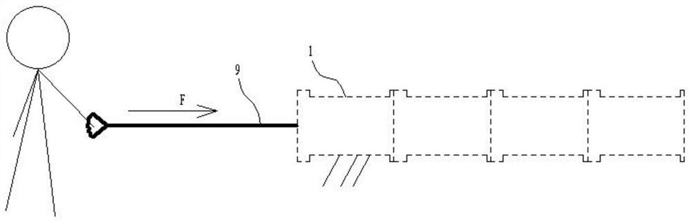
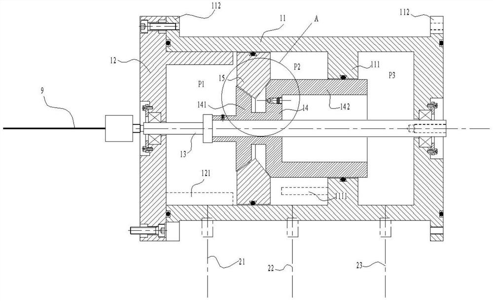
[0028] An autonomous combined auxiliary exercise device for orthopedic rehabilitation, comprising a tension rope 9 and a plurality of tension devices 1, the casing of the tension devices 1 is fixed, and the tension devices 1 are superimposed according to the force distribution requirements, and the tension rope 9 pulls the tension device 1 at the head for tension exercise. Such as ...


PUM


Abstract

The invention discloses an autonomous combined auxiliary exercise device for orthopedic rehabilitation, which comprises a tension rope and a tension device superimposed and used according to force distribution requirements, and the tension rope pulls the tension device at the head for tension exercise. The tension device includes a shell, an end cover, a tension shaft, a force distribution block, and a damping slider. One end of the shell is closed by the end cover, and the tension shaft runs through the shell and the end cover. A force distribution block is arranged on the tension shaft, and the force distribution block is located in the housing , the inner convex ring is set inward on the inner wall of the housing, and the damping slider is slidably installed on the inner wall of the housing. The damping slider is located between the end cover and the inner convex ring. The cylinders are connected together on the radial inner side near the tension shaft and fixed to the tension shaft by fasteners. The outer edge of the convex plate is located on the side of the damping slider close to the end cover, and the ring cylinder is located on the side of the damping slider away from the end cover. , the outer wall of the ring cylinder is in sliding contact with the inner convex ring; the gas is fed into or removed from the shell through three gas distribution pipes on the side wall of the shell.

Description

technical field [0001] The invention relates to the technical field of orthopedic rehabilitation training equipment, in particular to an autonomous combined auxiliary exercise equipment for orthopedic rehabilitation. Background technique [0002] Patients with orthopedic diseases need recovery training after treatment. These patients generally have limited limb strength and cannot perform a lot of weight-bearing exercises like ordinary people. Moreover, such trainers are prone to lose their strength, such as training with tension equipment. The pulling force is related to the stretching stroke. As long as there is a stretching stroke, there will be a pulling force. When the trainer is out of force, it is easy to drag the trainer and cause danger. [0003] In the prior art, there is no training equipment specially designed for orthopedic rehabilitation patients. Generally, common fitness equipment is used, and protective structures are added for tipping protection, etc., whil...

Claims


Application Information

Patent Timeline
Patent Type & Authority Patents(China)
IPC IPC(8): A63B23/12A63B71/00
CPCA63B23/12A63B71/0054
Inventor 丁莉应秋雯
Owner WUXI NO 9 PEOPLES HOSPITAL
Features
  • R&D
  • Intellectual Property
  • Life Sciences
  • Materials
  • Tech Scout
  • Unparalleled Data Quality
  • Higher Quality Content
  • 60% Fewer Hallucinations
Learn More