Gas-liquid or liquid-liquid mixed ultramicro bubble generation device

A technology of ultra-micro-bubble and generating device, applied in gas/vapor and liquid mixing, mixer, mixing method, etc., can solve the problems of low concentration of ultra-micro bubbles, large energy loss, and low overall number of turns, etc. The effect of liquid mixing efficiency, increasing contact time, and reducing energy loss

Pending Publication Date: 2021-06-11
宁波筑鸿纳米科技有限公司
View PDF1 Cites 2 Cited by
  • Summary
  • Abstract
  • Description
  • Claims
  • Application Information

AI Technical Summary

Problems solved by technology

However, the concentration of ultrafine bubbles produced by the existing ultrafine bubble generating device is too low, the number of ultrafine bubbles is too small, and it is not easy to preserve for a long time. Moreover, the existing ultrafine bubble generating device has high power, high energy consumption, and huge equipment It is bulky, has a small scope of application, is difficult to be widely used in the field of daily life, and cannot meet the actual needs of multi-purpose
[0004] In response to the above shortcomings, the applicant proposed a technical solution (hereinafter referred to as "the solution") of a convoluted ultra-fine bubble generating device (application publication number CN109316990A) on November 23, 2018. Micro-bubbles solve the problems of large volume, high power, high energy consumption and low efficiency of traditional bubble generators, and greatly expand the application range of ultra-micro bubble generators
However, there are still shortcomings in this solution: the inner flow chamber is placed outside, which cannot further compress the volume of the entire device, and its diameter is larger than the negative pressure chamber, resulting in a large energy loss from the negative pressure chamber into the inner flow chamber; liquid (or gas) in the During the process from the negative pressure chamber to the inner flow chamber and being stirred into a mixed liquid, the overall number of turns of the spiral acceleration is still not high, so the gas-liquid mixing efficiency and cutting and stirring efficiency will need to be improved

Method used


Image

  • Gas-liquid or liquid-liquid mixed ultramicro bubble generation device
  • Gas-liquid or liquid-liquid mixed ultramicro bubble generation device
  • Gas-liquid or liquid-liquid mixed ultramicro bubble generation device

Examples


Embodiment 1

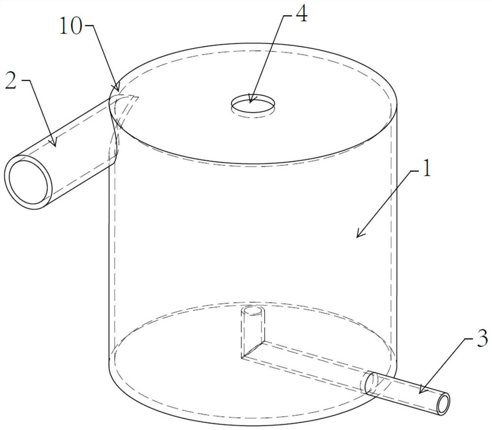
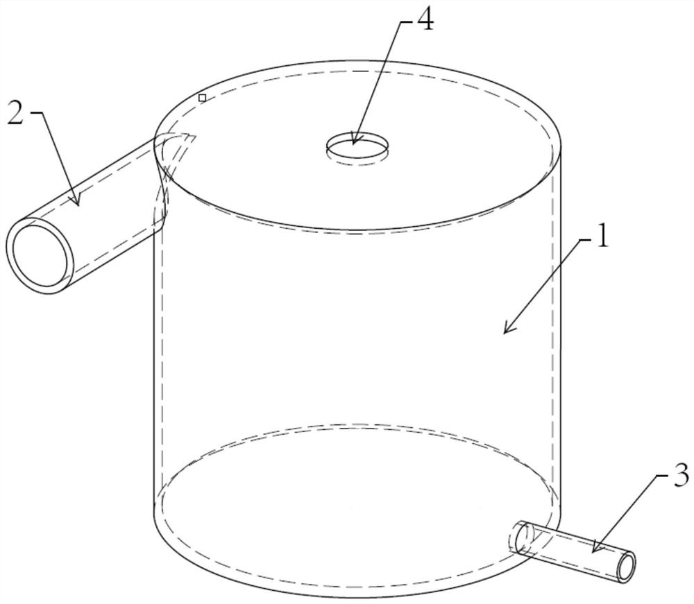
[0049] see Figure 1-2 , 4-9, the present invention provides a kind of technical scheme:

[0050] A gas-liquid or liquid-liquid mixed ultrafine bubble generating device, comprising:

[0051]The cavity 1 has an internal flow cavity 7 built in the cavity, and an external flow cavity 6 is formed between the internal flow cavity wall 5 of the internal flow cavity 7 and the cavity body 1;

[0052] The diversion port 10 is used to input the liquid I into the outer flow chamber 6;

[0053] The gas-liquid inlet 3 is used to input gas or liquid II into the inner flow chamber 7;

[0054] The liquid I enters the outer flow chamber 6 for a spiral acceleration, and then enters the inner flow chamber 7, and then continues to accelerate for a second time to generate negative pressure, and the gas or liquid II entering the gas-liquid inlet 3 is sucked and fully mixed and cut. , forming a gas-liquid;

[0055] The nozzle 4 is located in the center of the cavity 1 and is used for spraying ga...

Embodiment 2

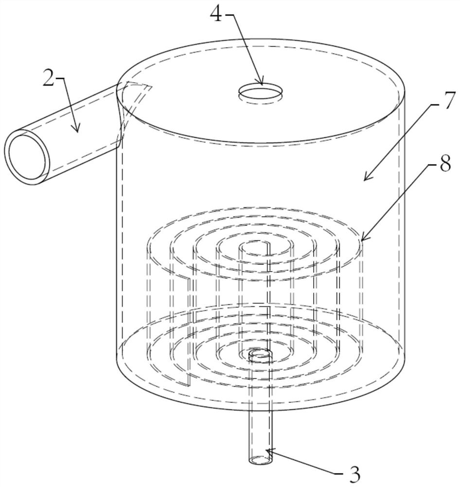
[0073] see image 3 , the present invention provides a kind of technical scheme, is basically the same as embodiment 1, and difference is:

[0074] A gas-liquid or liquid-liquid mixed ultrafine bubble generating device, comprising:

[0075] Chamber 1, including inner flow chamber 7, is used to accelerate, mix and cut liquid I and gas or liquid II, and form gas-liquid;

[0076] The diversion port 10 is used to input the liquid I into the cavity 1;

[0077] Gas-liquid inlet 3, used to input gas or liquid II into cavity 1;

[0078] The helical track 8 is placed in the cavity 1, and is used for spiral acceleration of liquid I and gas or liquid II; fully mixed.

[0079] The nozzle 4 is located in the center of the cavity 1 and is used for spraying gas and liquid.

[0080] In this embodiment, there is only one cavity, that is, the inner flow cavity 7 .

[0081] The technical principle of embodiment 2 is:

[0082] The liquid I (usually water) is connected to the diversion outer...


PUM

PropertyMeasurementUnit
angleaaaaaaaaaa

Abstract

The invention relates to the field of bubble generation, and concretely relates to a gas-liquid or liquid-liquid mixed ultramicro bubble generation device. The device comprises: a cavity comprising an inner flow cavity for accelerating, mixing and cutting liquid I and gas or liquid II and forming a gas-liquid mixture; a flow guide opening used for inputting the liquid I into the cavity; a gas-liquid inlet used for inputting the gas or the liquid II into the cavity; a spiral track arranged in the cavity, namely the inner flow cavity, and used for accelerating the liquid I and the gas or the liquid II in a rotating manner; and a nozzle positioned in the center of the cavity and used for spraying the gas and liquid. Gas-liquid or liquid-liquid mixing can be realized, namely, two fluids with different densities are mixed, the contact time and the contact area of gas-liquid mixing can be increased through the spiral track, gas and liquid can be subjected to repeated rotating and full contact, the gas-liquid mixing efficiency is improved, and the energy loss is reduced.

Description

technical field [0001] The invention relates to the technical field of bubble generation, in particular to a gas-liquid or liquid-liquid mixed ultrafine bubble generating device. Background technique [0002] In recent years, there have been several major social problems such as serious pollution of the water environment and serious shortage of water resources in various regions of our country. The country and the government have also attached great importance to water issues. The thirst for water is at an all-time high. [0003] Ultrafine bubbles or vacuoles are widely used in actual production and life. Ultrafine bubbles can be used in various fields of life, such as fruit and vegetable cleaning, aquaculture, crop production increase, sewage purification, health drinks, medical treatment, etc. Ultrafine vacuoles can be used Allow solutions of different densities to fully mix, used in industrial, medical, and new energy fields. However, the concentration of ultrafine bubb...

Claims


Application Information

Patent Timeline
Patent Type & Authority Applications(China)
IPC IPC(8): B01F5/00B01F5/06B01F3/04B01F3/08
CPCB01F23/20B01F23/40B01F23/45B01F25/00B01F25/10B01F25/40
Inventor 赵卓维
Owner 宁波筑鸿纳米科技有限公司
Why Eureka
Try Eureka