Four-roller hydraulic transmission plate bending machine

A technology of hydraulic transmission and plate rolling machine, applied in safety equipment, feeding device, positioning device, etc., can solve problems such as affecting efficiency, abnormal jitter, affecting product quality, etc., to reduce potential safety hazards, ensure stable processing, and reduce abnormality dithering effect

Inactive Publication Date: 2021-06-11
许攀
View PDF0 Cites 1 Cited by
  • Summary
  • Abstract
  • Description
  • Claims
  • Application Information

AI Technical Summary

Problems solved by technology

[0003] 1. When the existing plate rolling machine rolls the steel plate, there is no device that can hold it up at the rolled end, and it is easy to shake when rotating, which affects the quality of the rolling, and the rolled steel plate produces relatively large Large internal stress affects the quality of the product;
[0004] 2. According to the needs of the equipment for the angle of the steel coil, the traditional equipment cannot support and fix the end of the coiling process, resulting in abnormal vibration during the subsequent processing process, which is easy to scratch the workers, thus causing certain safety hazards;
[0005] 3. More processes are required to process the plate with rust on the surface, which affects the efficiency

Method used


Image

  • Four-roller hydraulic transmission plate bending machine
  • Four-roller hydraulic transmission plate bending machine
  • Four-roller hydraulic transmission plate bending machine

Examples


Embodiment Construction

[0036] The technical solutions in the embodiments of the present invention will be clearly and completely described below in conjunction with the accompanying drawings in the embodiments of the present invention. Apparently, the described embodiments are only some, not all, embodiments of the present invention. Based on the embodiments of the present invention, all other embodiments obtained by persons of ordinary skill in the art without making creative efforts belong to the protection scope of the present invention.

[0037] see Figure 1 to Figure 6 , the present invention provides a technical solution:

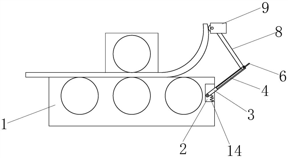
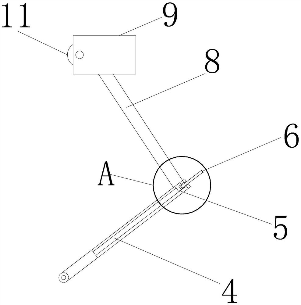
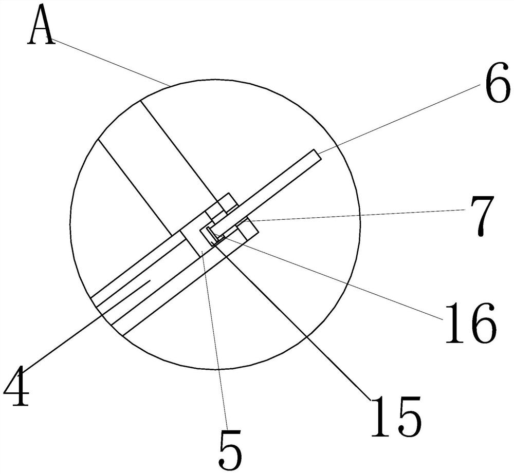
[0038] Such as Figure 1 to Figure 6 As shown, a four-roller hydraulic transmission plate rolling machine includes a plate rolling machine main body 1, and a cavity 2 is opened on one side of the outer surface of the plate rolling machine main body 1 near the upper end, and one side of the cavity 2 is outside. A first groove 12 is opened on the surface, and a second rota...


PUM


Abstract

The invention discloses a four-roller hydraulic transmission plate bending machine which comprises a plate bending machine body. A cavity is formed in one side of the plate bending machine body, and a first groove is formed in one side of the interior of the cavity; a second rotating shaft is arranged in the first groove, and a supporting rod is hinged to one side of the second rotating shaft; a sliding groove is formed in the position, close to the center, in the supporting rod; a threaded hole is formed in the right end of the supporting rod, and a threaded rod is in threaded connection with the interior of the threaded hole; a sliding block is slidably connected with the interior of the sliding groove, and the end, away from the interior of the sliding groove, of the sliding block is fixed to one end of a connecting rod; and fixed clamping plates are fixed to the other end of the connecting rod, and a pulley is installed between the fixed clamping plates. According to the bending machine, a plate can be effectively supported, and meanwhile the supporting position can be adjusted according to the size of the plate; therefore, the applicability of the machine is improved, and in addition, the pulley is rotated to clean the surface of the plate; and the stress of the plate is improved, and the product quality is improved.

Description

technical field [0001] The invention relates to the technical field of plate bending machines, in particular to a four-roller hydraulic drive plate rolling machine. Background technique [0002] The plate rolling machine is the main equipment for producing cylindrical, arc or conical workpieces through the rotating roller shaft. Among them, the three-roll plate rolling machine and the four-roll plate rolling machine are more commonly used; the current plate rolling machines are relatively Large, the lower half of the plate rolling machine is generally placed below the ground, and the roller body is above the ground for easy loading; the working principle of the plate rolling machine is to drive the active roll to rotate through the drive system, and squeeze the rolled plate together with the passive roll to drive The rolled sheet moves upwards, and the rolled sheet is permanently plastically deformed by the pressure between the rollers. [0003] 1. When the existing plate r...

Claims


Application Information

Patent Timeline
Patent Type & Authority Applications(China)
IPC IPC(8): B21D5/14B21D43/00B21D55/00
CPCB21D5/14B21D43/003B21D55/00
Inventor 许攀余兆勇
Owner 许攀
Why Eureka
Try Eureka