
Rapid pressing machine for flywheel gear ring

A flywheel ring gear and pressing machine technology, which is applied in metal processing equipment, metal processing, manufacturing tools, etc., can solve the problems of high labor intensity and low efficiency of workers, and achieve the effect of improving efficiency, simplifying structure and reducing labor intensity.

Active Publication Date: 2021-06-11
重庆新炬鑫机械有限公司
View PDF8 Cites 1 Cited by
  • Summary
  • Abstract
  • Description
  • Claims
  • Application Information

AI Technical Summary

Problems solved by technology

[0003] The present invention intends to provide a flywheel ring gear fast pressing machine to solve the problems of manual pressing of the ring gear on the flywheel body, low efficiency and high labor intensity of workers

Method used


Image

  • Rapid pressing machine for flywheel gear ring
  • Rapid pressing machine for flywheel gear ring
  • Rapid pressing machine for flywheel gear ring

Examples


Embodiment Construction

[0021] The following is further described in detail through specific implementation methods:

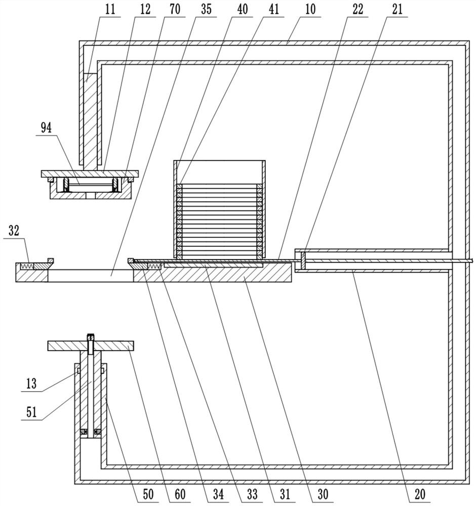
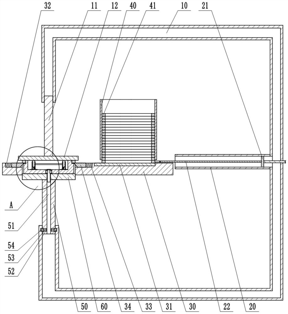
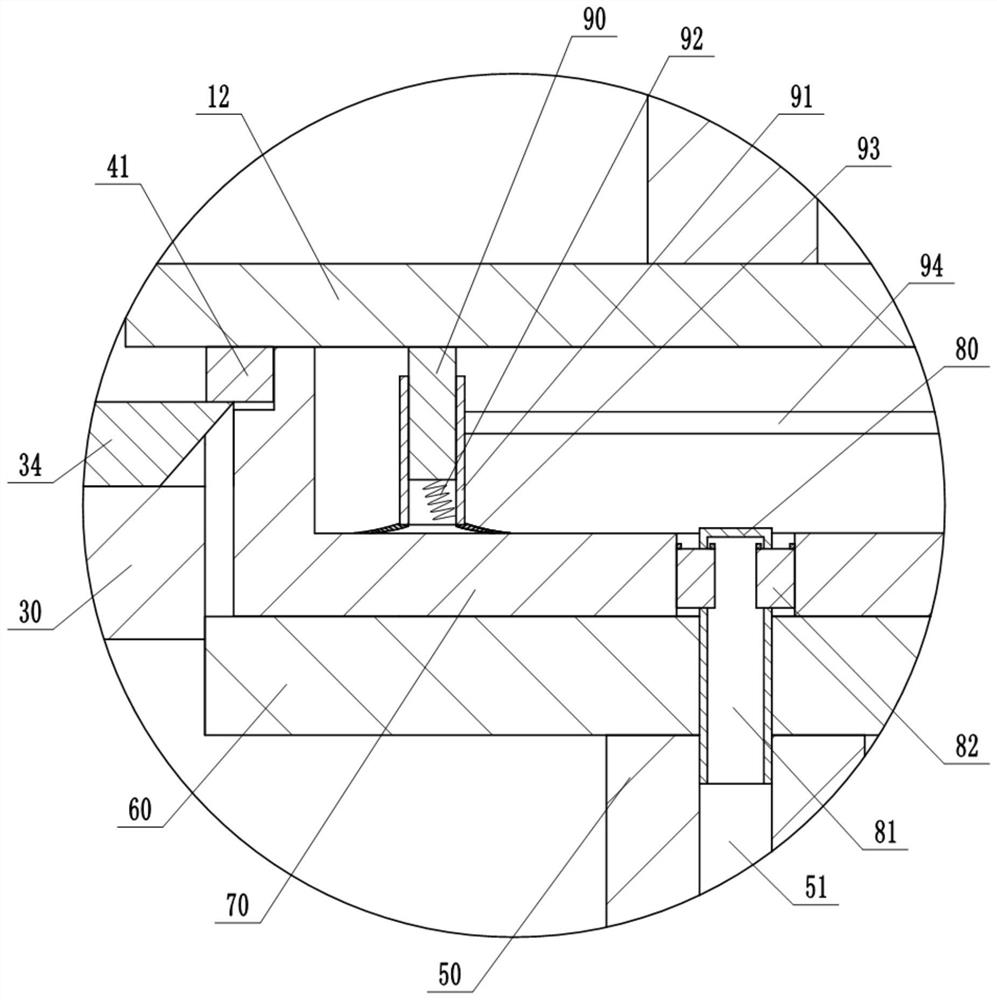
[0022] The reference signs in the drawings of the description include: pressing column 10, first pressing column 11, pressing plate 12, card slot 13, fixing cylinder 20, pushing plate 21, pushing rod 22, workbench 30, heating mechanism 31, slide Groove 32, reset member 33, slide block 34, port 35, storage barrel 40, ring gear 41, second pressure column 50, through groove 51, accommodation groove 52, first elastic member 53, wedge 54, support seat 60. Flywheel body 70, post 80, groove 81, clamp block 82, pressing rod 90, sleeve 91, second elastic member 92, suction cup 93, connecting rod 94.

[0023] This embodiment is basically as figure 1 , figure 2Shown: flywheel ring gear fast pressing machine, including frame, workbench 30, pressing column 10, fixed cylinder 20, material storage cylinder 40, suction mechanism, power mechanism and heating for heating ring gear 41 agency31. Th...


PUM


Abstract

The invention belongs to the technical field of flywheel machining devices, and particularly relates to a rapid pressing machine of a flywheel gear ring. The rapid pressing machine comprises a workbench, a pressing column, a fixed barrel, a power mechanism, a storage barrel and a heating mechanism. A through cavity is formed in the pressing column, a first press column is slidably connected in one side of the pressing column, and a second press column is slidably connected in the other side of the pressing column. The pressing column is filled with transmission fluid. A pressing plate is arranged on the first press column, and a supporting seat is arranged on the second press column. A through groove is formed in the second press column, an inserting column with the upper portion penetrating through the supporting seat is fixed in the through groove, and a groove is formed in the inserting column. Multiple clamping blocks are slidably connected to the side wall of the inserting column. A through hole allowing a flywheel body to pass through is formed in the workbench. The storage barrel is located above the workbench, and the distance between the lower end of the storage barrel and the workbench is 1-1.5 gear ring thicknesses. The fixed barrel communicates with the pressing column, and a push column is slidably connected in the fixed barrel. By using the scheme, the problems that when the gear ring is manually pressed on the flywheel body, the efficiency is low, and the labor intensity of workers is high can be effectively solved.

Description

technical field [0001] The invention belongs to the technical field of flywheel processing devices, and in particular relates to a flywheel ring gear fast pressing machine. Background technique [0002] Currently, electric start flywheels on general gasoline engines are usually gray cast iron or aluminum. The main part of the gray cast iron flywheel is made of sand casting, and the ring gear used to connect the flywheel with the chain (the one-way gear that matches the starter motor) is a machined part, and the ring gear is assembled on the body by hot pressing . When producing and processing the electric starter flywheel on gasoline engines, it is necessary to press the ring gear on the main body of the flywheel. The commonly used pressing method is: the worker has a flame gun to heat the ring gear, and the ring gear is heated by the principle of thermal expansion and contraction. Then use a tool such as a hammer to knock the ring gear on the flywheel body. After the ring...

Claims


Application Information

Patent Timeline
Patent Type & Authority Applications(China)
IPC IPC(8): B23P19/027
CPCB23P19/027
Inventor 唐微涵
Owner 重庆新炬鑫机械有限公司
Learn More