
Stamping and grinding device

A grinding table and grinding rod technology, applied in grinding/polishing safety devices, grinding machines, grinding/polishing equipment, etc., can solve the problems of low thickness control accuracy and achieve the effect of easy control

Active Publication Date: 2021-06-11
重庆大江国立精密机械制造有限公司
View PDF11 Cites 0 Cited by
  • Summary
  • Abstract
  • Description
  • Claims
  • Application Information

AI Technical Summary

Problems solved by technology

[0004] The purpose of the present invention is to solve the problem that the thickness control accuracy of the traditional stamping parts is low when the thickness is polished

Method used


Image

  • Stamping and grinding device
  • Stamping and grinding device
  • Stamping and grinding device

Examples


Embodiment Construction

[0031] In order to further explain the technical means and effects of the present invention to achieve the intended purpose of the invention, the specific implementation, structure, features and effects of the present invention will be described in detail below in conjunction with the accompanying drawings and preferred embodiments.

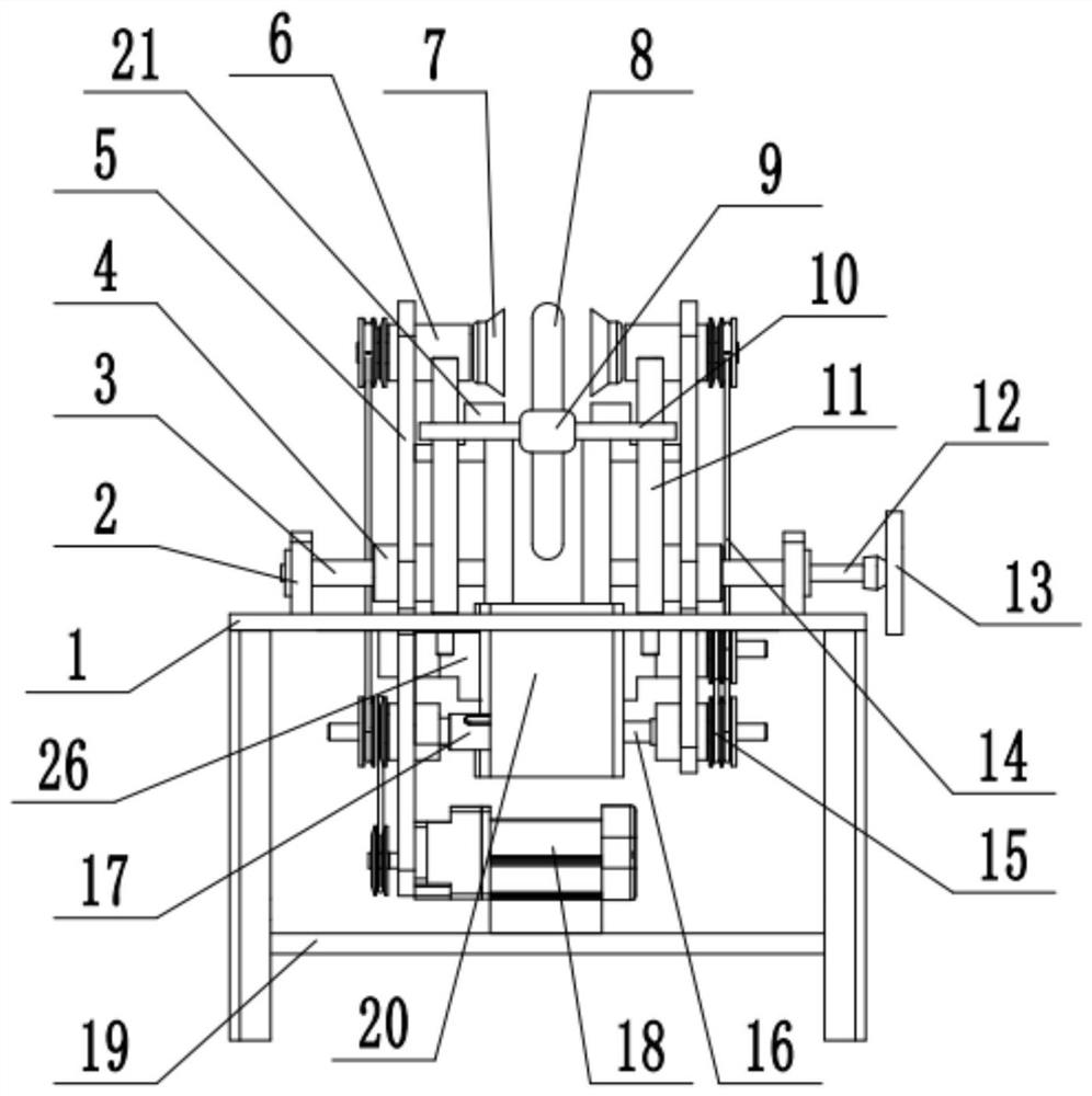
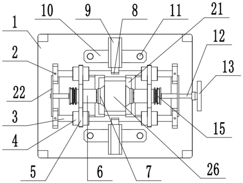
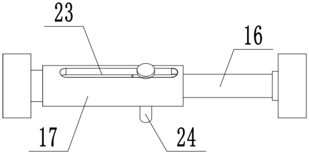
[0032] The reference signs in the drawings of the description include: grinding table 1, column 2, support rod 3, sliding sleeve 4, support plate 5, grinding rod 6, grinding wheel 7, clamping plate 8, first cylinder 9, mounting plate 10 , limit rod 11, transmission rod 12, handrail 13, transmission belt 14, transmission wheel 15, auxiliary shaft 16, main shaft 17, motor 18, support plate 19, second cylinder 20, waste recycling tank 21, fixed plate 22, function Groove 23, function induction 24, size adjustment member 25, dust suppression box 26, sealing cover 27, transmission shaft 28, water-repelling plate 29, negative pressure blade 30, water inl...


PUM


Abstract

The invention relates to the technical field of grinding equipment, and particularly discloses a stamping and grinding device. The device comprises a grinding table, a grinding mechanism arranged on the grinding table and a power mechanism providing power for the grinding mechanism, wherein a grinding groove is arranged in the grinding table; the grinding mechanism comprises a plurality of supporting rods arranged over the grinding groove and supporting plates symmetrically arranged on the supporting rods in a sliding mode; grinding rods are symmetrically and rotationally arranged at the upper ends of the supporting plates; grinding wheels are detachably connected to the free ends of the grinding rods; a transmission rod in threaded connection with the supporting plates is arranged on the grinding table; the threaded rotation modes of the two ends of the transmission rod are opposite; size adjusting pieces are symmetrically arranged at the two ends of the transmission rod; a plurality of limiting rods are symmetrically arranged on the grinding table; first air cylinders are symmetrically arranged on the limiting rods in a sliding mode; second air cylinders used for controlling the height of the first air cylinders are symmetrically arranged on the grinding table; and clamping plates are arranged at the working ends of the first air cylinders. The invention aims to solve the problem that the thickness control accuracy is low when a traditional stamping part is subjected to thickness grinding.

Description

technical field [0001] The application relates to the technical field of grinding equipment, and specifically discloses a stamping grinding device. Background technique [0002] Stamping parts are formed by applying external force to plates, strips, pipes and profiles by presses and molds to cause plastic deformation or separation to obtain workpieces (stamping parts) of required shape and size. Stamping and forging belong to plastic processing (or pressure processing) and are collectively called forging. The blanks for stamping are mainly hot-rolled and cold-rolled steel sheets and strips. [0003] In the stamping process, it is often necessary to adjust multiple thicknesses on a stamped part. However, due to the limitation of raw materials and in order to ensure the thickness of the maximum position during stamping, it may not be possible to stamp to the specified thickness in relatively thin places. To adapt to the position, at this time, it is necessary to grind the st...

Claims


Application Information

Patent Timeline
Patent Type & Authority Applications(China)
IPC IPC(8): B24B27/00B24B55/06B24B55/12
CPCB24B27/00B24B27/0092B24B55/06B24B55/12Y02P70/10
Inventor 胡茜王伟韩国龙
Owner 重庆大江国立精密机械制造有限公司
Learn More