
Solid raw material crushing device and method thereof
A raw material pulverization and equipment technology, applied in separation methods, chemical instruments and methods, filtration and separation, etc., can solve the problems of poor pulverization effect of solid raw materials, splashing of debris, insufficient and thorough pulverization, etc.
- Summary
- Abstract
- Description
- Claims
- Application Information
AI Technical Summary
Problems solved by technology
Method used
Image

Examples
Embodiment 1
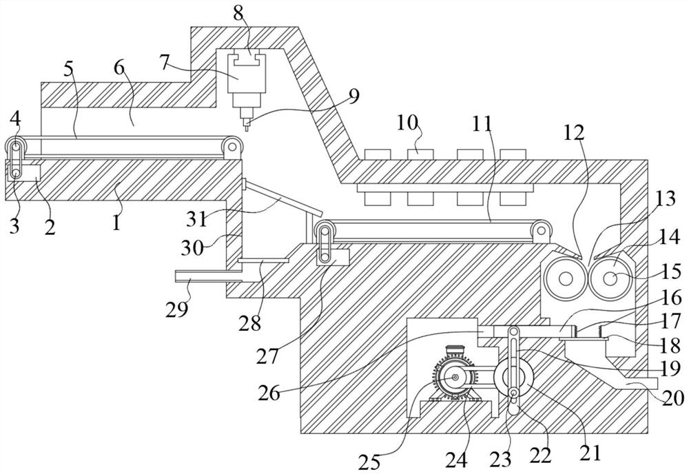
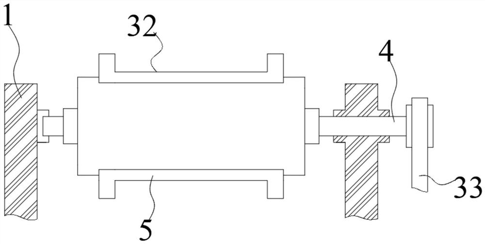
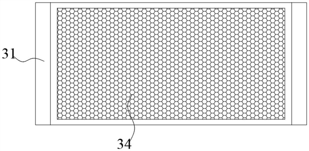
[0024] Embodiment one, by Figure 1-4Given, the present invention is a kind of solid raw material crushing equipment and method thereof, including a body 1, a cutting groove 6 is opened on the left outer wall of the body 1, and a support shaft 4 is rotatably connected to the inner wall of the bottom surface of the cutting groove 6, and the support One end of the shaft 4 is slidably connected to the inner wall of the belt A33, and the inner wall of the belt A33 is slidably connected to one end of the rotating shaft A3, and the other end of the rotating shaft A3 is rotatably connected to the inner wall of the motor A2, and the upper surface of the cutting groove 6 is provided There is a slide rail 8, and the outer wall of the bottom surface of the slide rail 8 is slidably connected with an electric slider 7, the outer wall of the bottom surface of the electric slider 7 is fixedly connected with a water jet cutting machine 9, and the inner wall of the bottom surface of the cutting...
PUM
 Abstract
Description
Claims
Application Information