
A hydraulic machining equipment with protective mechanism

A technology of hydraulic machinery and processing equipment, which is applied in the field of hydraulic mechanical processing equipment with a protective mechanism, which can solve the problems of reduced cutting accuracy, inability to guide and position, and skewed plates to achieve the effect of improving efficiency

Active Publication Date: 2022-05-06
佛山市顺德区科雅力健锻压机床有限公司
View PDF6 Cites 0 Cited by
  • Summary
  • Abstract
  • Description
  • Claims
  • Application Information

AI Technical Summary

Problems solved by technology

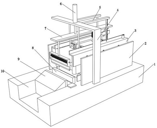
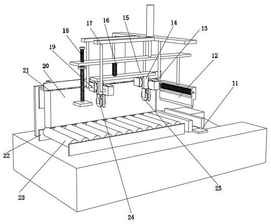
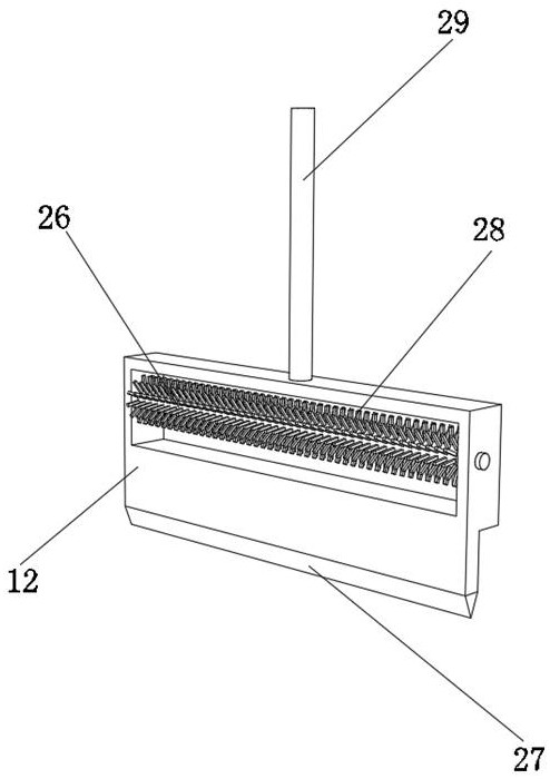
[0005] The purpose of the present invention is to solve the disadvantages existing in the prior art that the plate cannot be effectively guided and positioned when it is moving during the cutting process, resulting in the plate being easily skewed during the cutting process and resulting in reduced cutting accuracy. A hydraulic machining equipment with protective mechanism is proposed

Method used


Image

  • A hydraulic machining equipment with protective mechanism
  • A hydraulic machining equipment with protective mechanism
  • A hydraulic machining equipment with protective mechanism

Examples


Embodiment Construction

[0030] The technical solution of this patent will be further described in detail below in conjunction with specific embodiments.

[0031] Embodiments of the present patent are described in detail below, examples of which are shown in the drawings, wherein the same or similar reference numerals designate the same or similar elements or elements having the same or similar functions throughout. The embodiments described below by referring to the figures are exemplary and are only used for explaining the patent, and should not be construed as limiting the patent.

[0032] In the description of this patent, it is to be understood that the terms "center", "upper", "lower", "front", "rear", "left", "right", "vertical", "horizontal", The orientation or positional relationship indicated by "top", "bottom", "inner", "outer", etc. is based on the orientation or positional relationship shown in the drawings, and is only for the convenience of describing this patent and simplifying the des...


PUM


Abstract

The invention discloses a hydraulic mechanical processing equipment with a protective mechanism, which relates to the technical field of hydraulic mechanical processing equipment; in order to avoid skewing of wood during cutting; it specifically includes a base and a guide assembly, and the outer wall of the top of the base is fixed with a L Type frame, the outer wall of one side of the L-shaped frame is fixed with two connecting plates by screws, the top outer wall of the L-shaped frame is fixed with a hydraulic press by bolts, the output end of the hydraulic machine is fixed with a lifting plate by bolts, and the bottom of the lifting plate The outer wall is fixed with a spring expansion column 1 by screws, and the bottom outer wall of the spring expansion column 1 is fixed with two supports 1 by screws, and the inner walls of the two supports 1 are all rotated by a bearing to have a pulley 2. The present invention can control its output end to move up and down by being provided with a hydraulic machine, thereby can drive the adjustment board to move up and down, and the bottom of the second pulley will generate a downward driving force on the outer wall of the connecting rope during the up and down movement of the adjustment board.

Description

technical field [0001] The invention relates to the technical field of hydraulic machining equipment, in particular to a hydraulic machining equipment with a protection mechanism. Background technique [0002] Because hydraulic machinery can generate stable pressure at the output end, and the service life of the hydraulic machine is long, there are many industries that use hydraulic machines for production and processing. In the field of wood production, wood needs to be cut to ensure that its length can reach the required specifications. And the standard, the current hydraulic cutting usually fixes the cutter at the output end of the hydraulic press, but other equipment is needed to fix the wood during the cutting process, which reduces the efficiency and also increases additional costs [0003] After searching, the Chinese patent application number is CN201220559027.0, which discloses a kind of hydraulic machining equipment, which solves the problem that there is no hydrau...

Claims


Application Information

Patent Timeline
Patent Type & Authority Patents(China)
IPC IPC(8): B27C5/00B27C9/00B27G3/00
CPCB27C5/006B27C9/00B27G3/00
Inventor 安亚雷
Owner 佛山市顺德区科雅力健锻压机床有限公司
Learn More