
Design process of double railway suspended vehicle for automated transportation based on dynamics optimization

A design process and conveyor technology, applied in conveyors, conveyor objects, mechanical conveyors, etc., can solve problems such as affecting stability, different torques of internal and external motors, track deformation, etc., to improve operation efficiency, ensure reliability, The effect of ensuring reliability and accuracy

Inactive Publication Date: 2021-06-11
DESIGN INST NO 9 MINISTRY OF MECHINE BUILDING
View PDF0 Cites 0 Cited by
  • Summary
  • Abstract
  • Description
  • Claims
  • Application Information

AI Technical Summary

Problems solved by technology

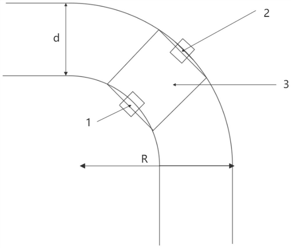
[0006] The purpose of the present invention is to solve the problem that the torque of the inner and outer motors is often different due to the inertial force and the difference between the inner and outer tracks of the track when the double-gauge suspension self-conveyor is transporting heavy goods. Since the selection of motor power and torque of the conveyor is optimized, and when transporting heavy goods, there will inevitably be different degrees of track deformation with the long-term operation. At the same time, transporting heavy goods will further aggravate the aforementioned phenomenon when cornering. In the case of track deformation, stability will be affected, so as to solve the above-mentioned problems for the position, the present invention provides a design process of double-track suspension self-conveyor based on dynamic optimization, which includes:

Method used


Image

  • Design process of double railway suspended vehicle for automated transportation based on dynamics optimization
  • Design process of double railway suspended vehicle for automated transportation based on dynamics optimization
  • Design process of double railway suspended vehicle for automated transportation based on dynamics optimization

Examples


Embodiment Construction

[0051] The above and other technical features and advantages of the present invention will be described in more detail below in conjunction with the accompanying drawings.

[0052] Preferred embodiments of the present invention are described below with reference to the accompanying drawings. Those skilled in the art should understand that these embodiments are only used to explain the technical principles of the present invention, and are not intended to limit the protection scope of the present invention.

[0053] It should be noted that, in the description of the present invention, terms such as "upper", "lower", "left", "right", "inner", "outer" and other indicated directions or positional relationships are based on the terms shown in the accompanying drawings. The direction or positional relationship shown is only for convenience of description, and does not indicate or imply that the device or element must have a specific orientation, be constructed and operated in a spec...


PUM


Abstract

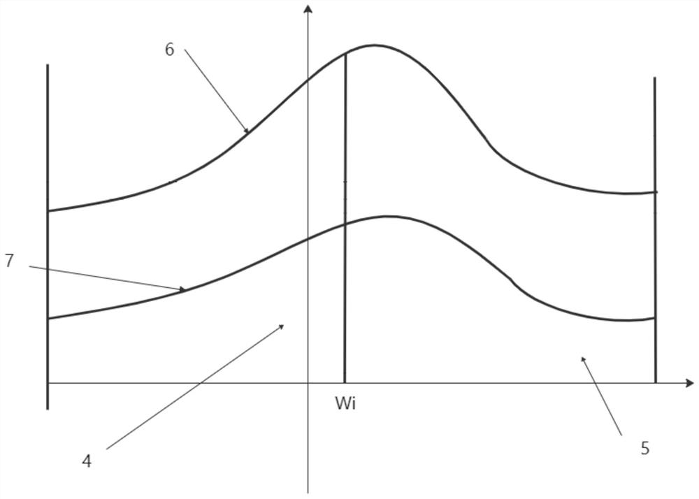
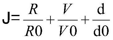
The invention relates to a design process of a double railway suspended vehicle for automated transportation based on dynamics optimization. The design process comprises the following steps of constructing a torque change curve graph of a first motor and a second motor of a conveyor, intercepting a curve section corresponding to the torque change curve graph when the conveyor turns, analyzing the corresponding curve section, analyzing an over-bending line segment in a segmented mode to represent the torque change condition during turning and the operation condition of the motor more accurately, correcting calculating parameters through a series of operations and considering the deformation condition of an operation orbit, and finally the optimal operation power and the optimal motor output torque of the motor. According to the design process, the stability and accident resistance of the conveyor are improved, and the most suitable motor is selected under the condition that the cost of the conveyor is saved.

Description

technical field [0001] The invention belongs to the field of conveyors, in particular to a dynamic optimization-based double-track suspension self-conveyor design process. Background technique [0002] In the early 1990s, my country began to use suspension transport equipment in the form of self-propelled trolley conveyors. So far, monorail suspension self-propelled conveyors have been mostly used in the fields of light industry, automobiles and construction machinery. With the development of light industry, automobile and other industries, there is an urgent need for conveying equipment suitable for large and wide-body workpieces. The single-rail suspension self-conveyor can no longer fully meet the conveying requirements of the workpiece. On this basis, the task of developing a trial-manufactured double-rail suspension self-propelled conveyor more and more urgent. Since the double-track suspension self-conveyor adopts 4-point suspension, it has good stability during the ...

Claims


Application Information

Patent Timeline
IPC IPC(8): B65G35/00B65G43/00
CPCB65G35/00B65G43/00
Inventor 刘世新李晶明李传州
Owner DESIGN INST NO 9 MINISTRY OF MECHINE BUILDING
Learn More