Gas-based reduction simulation device and gas-based reduction simulation method

A simulation device and simulation method technology, applied in fluidized bed furnaces and other directions, can solve problems such as low accuracy of experimental results, and achieve the effects of ensuring setting stability, facilitating connection, and reducing secondary oxidation.

Active Publication Date: 2021-06-11
CENT IRON & STEEL RES INST +1
View PDF8 Cites 0 Cited by
  • Summary
  • Abstract
  • Description
  • Claims
  • Application Information

AI Technical Summary

Problems solved by technology

[0004] In view of the above analysis, the present invention aims to provide a gas-based reduction simulation device and a gas-based reduction simulation method, which solves the problems of secondary oxidation of reduced materials and low accuracy of experimental results in the prior art

Method used


Image

  • Gas-based reduction simulation device and gas-based reduction simulation method
  • Gas-based reduction simulation device and gas-based reduction simulation method
  • Gas-based reduction simulation device and gas-based reduction simulation method

Examples


Embodiment 1

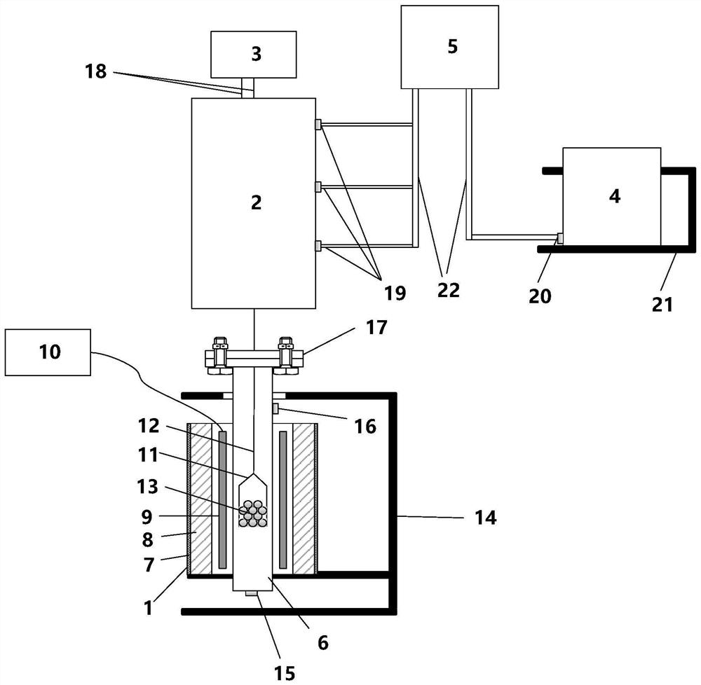
[0096] Step A: Set the temperature of the furnace tube, the reduction temperature is 1200°C, the temperature rise rate in the furnace tube is 10°C / min, and nitrogen is introduced into the furnace tube through the reduction air inlet, and the nitrogen flow rate is 1L / min;

[0097] Step B: When the temperature in the furnace tube reaches 1200°C, lower the upper flange with one end of the protector hanging wire together with the loading basket lifted by the lower tube loading basket hanging wire through the hoisting device, and place the loading The basket is put into the furnace tube, the upper flange and the lower flange are aligned and fixed with bolts;

[0098] Step C: Set the reduction air inlet to feed carbon monoxide into the furnace tube, the gas flow rate is 1L / min, the pressure inside the furnace tube is 0.005Mpa, and the reduction time is 20min;

[0099] Step D: After the experiment is completed, change the gas from the reduction inlet to the furnace tube to nitrogen, ...

Embodiment 2

[0104] Step A: Lower the upper flange with one end of the protector hanging wire together with the charging basket hoisted by the lower tube loading basket hanging wire through the hoisting device, and put the charging basket into the furnace tube, the upper flange Align with the lower flange and fix with bolts;

[0105] Step B: Set the temperature of the furnace tube, the reduction temperature is 1200°C, the temperature rise rate in the furnace tube is 10°C / min, and nitrogen is introduced into the furnace tube through the reduction air inlet, and the nitrogen flow rate is 1L / min;

[0106] Step C: When the temperature in the furnace tube reaches 1200°C, set the reduction air inlet to feed hydrogen into the furnace tube, the gas flow rate is 1L / min, the pressure in the furnace tube is 0.01Mpa, and the reduction time is 30min;

[0107] Step D: After the experiment is completed, change the gas from the reduction inlet to the furnace tube to nitrogen, and then open the bolts of th...


PUM


Abstract

The invention discloses a gas-based reduction simulation device and a gas-based reduction simulation method, and belongs to the technical field of gas-based thermal simulation experiments in high-temperature laboratories.The problem of lower accuracy of experimental results due to secondary oxidation of reduced materials in the prior art is solved. The gas-based reduction simulation device comprises a reduction furnace, a protector, a cooler and a protective gas supply unit; the protective gas supply unit communicates with the protector; protective gas in the protector is positive pressure; an experimental material is arranged in the reduction furnace; an opening of the protector is arranged downwards; the protector is buckled at the top end of the reduction furnace; and the experimental material is moved out of the reduction furnace, enters the protector and is conveyed to the cooler. The gas-based reduction simulation method comprises the following steps of: performing gas-based reduction on an experimental material in a reduction furnace; buckling the protector at the top end of the reduction furnace; starting a protective gas supply unit, and moving the experimental material out of the reduction furnace to enter the protector; moving the protector, and conveying the experimental material into the cooler. The gas-based reduction simulation device and the gas-based reduction simulation method can be used for gas-based reduction simulation.

Description

technical field [0001] The invention belongs to the technical field of gas-based thermal simulation experiments in high-temperature laboratories, and in particular relates to a gas-based reduction simulation device and a gas-based reduction simulation method. Background technique [0002] The high-temperature reduction experimental furnace is used to reduce the material. Due to the high temperature of the reduced material, oxidation reaction is easy to occur. Therefore, the reduced material needs to be protected by atmosphere. [0003] In the existing gas-based reduction furnace, when cooling is required, the high-temperature sample is directly taken out and put into a crucible or container with a non-oxidizing atmosphere. It is impossible to fully guarantee the atmosphere protection of the materials in the process of discharging and feeding, which may easily cause secondary oxidation of the materials, resulting in low accuracy of the experimental results. Contents of the ...

Claims


Application Information

Patent Timeline
Patent Type & Authority Applications(China)
IPC IPC(8): C21B13/00
CPCC21B13/0073
Inventor 王锋徐洪军高建军周和敏齐渊洪严定鎏林万舟
Owner CENT IRON & STEEL RES INST
Why Eureka
Try Eureka