Offshore wind power single pile-friction wing composite foundation and its construction method

A technology for offshore wind power and composite foundations, which is applied in foundation structure engineering, wind power generation, sheet pile walls, etc., and can solve problems such as the inability to realize the horizontal bearing capacity of single pile foundations, the easy bending and twisting of the wing plate structure, and the difficulty of construction , to achieve the effect of reducing the difficulty of production and transportation, simple construction, and improving the horizontal resistance of the soil

Active Publication Date: 2022-04-12
CHINA THREE GORGES CORPORATION +1
View PDF8 Cites 0 Cited by
  • Summary
  • Abstract
  • Description
  • Claims
  • Application Information

AI Technical Summary

Problems solved by technology

However, for offshore wind farms with a thicker silt layer above the seabed cover, it is difficult for the rockfill body in the monopile and rockfill composite foundation, and the cylinder in the monopile and cylinder composite foundation to pass through the silt layer located / The bearing layer is embedded in the bearing layer to effectively play its supporting role. Although the single pile and friction ring composite foundation can pass through the mud layer, the bearing capacity of the composite foundation can only be increased by the friction and support provided by the support wing plate and friction ring, but the friction The ring only relies on the friction force between the structure wall and the surrounding soil and the passive soil resistance, and the single pile and the friction ring need to be fabricated, transported, and constructed in one piece, and the construction is difficult; The load is larger, and the wing plate structure in the single pile and wing plate composite foundation is prone to bending, twisting, and even buckling, which cannot achieve the purpose of improving the horizontal bearing capacity of the single pile foundation

Method used


Image

  • Offshore wind power single pile-friction wing composite foundation and its construction method
  • Offshore wind power single pile-friction wing composite foundation and its construction method
  • Offshore wind power single pile-friction wing composite foundation and its construction method

Examples


Embodiment Construction

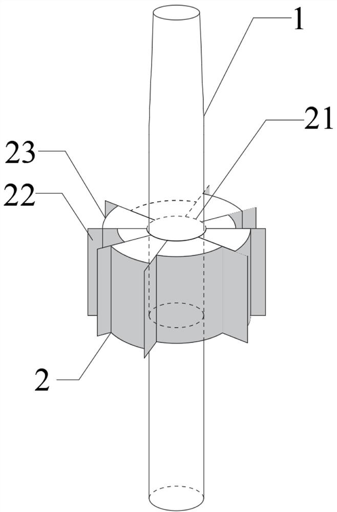
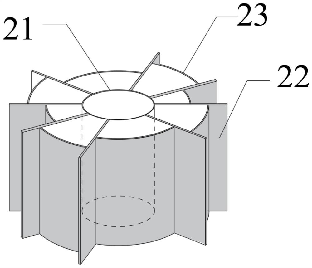
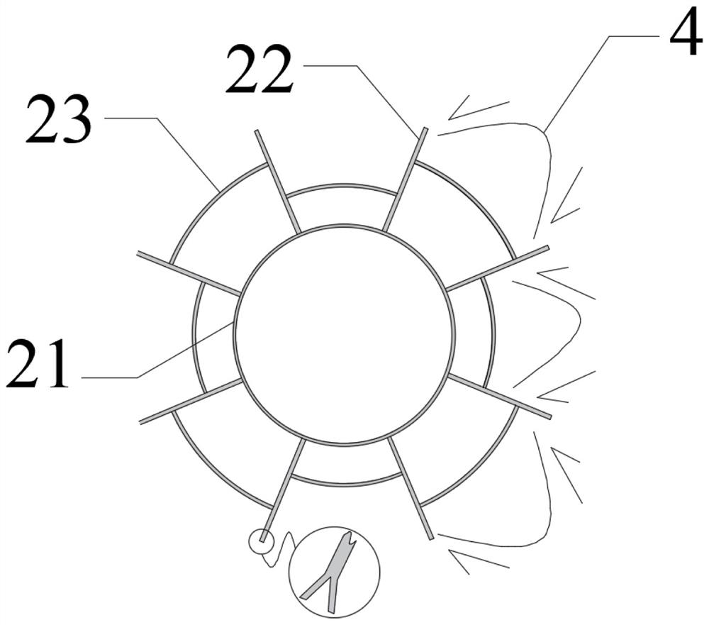
[0037] Such as Figure 1-Figure 8 Among them, an offshore wind power monopile-friction wing composite foundation, which includes a single pile 1 and a friction wing 2; The outer wall of the force tube 21 is connected, and the ring wing 23 is located outside the force transmission tube 21 and connected with the side wing 22; the side wing 22, the inner side of the ring wing 23 and the outer wall of the force transmission tube 21 form an axial through structure. The conical transition section 11 of the single pile 1 goes deep into the bearing layer of the seabed, and the force transmission tube 21 of the friction wing 2 located in the bearing layer is in close contact with the conical transition section 11 of the single pile 1, and the friction wing 2 is axially Through the structure, it is convenient to embed the bearing layer of the seabed. The structure of the wing 22 and the ring wing 23 of the friction wing 2 increases the interaction area between the composite foundation a...


PUM


Abstract

An offshore wind power monopile-friction wing composite foundation and its construction method, which includes a single pile and a friction wing, the friction wing is connected to the single pile through a force transmission tube, and the conical transition section of the single pile goes deep into the bearing layer of the seabed and is located at The force transmission tube of the friction wing in the force-bearing layer is in close contact with the conical transition section of the single pile, the side wings of the friction wing are connected to the outer wall of the force transmission tube, and the ring wings are arranged inside the included angle of the side wings. The friction wing of the present invention is a penetrating structure in the axial direction, which is convenient to pass through the seabed silt layer and embed into the force-bearing layer; The soil arch effect is generated between the wings, which significantly improves the resistance of the soil. The friction wing increases the interaction area between the structure and the soil, and improves the bearing capacity of the single pile-friction wing composite foundation.

Description

technical field [0001] The invention belongs to the technical field of offshore wind power foundation and construction, and relates to an offshore wind power single pile-friction wing composite foundation and a construction method thereof. Background technique [0002] Domestic offshore wind power foundation structures are mainly based on single pile foundations, jacket foundations, high pile cap foundations, and barrel foundations. The single pile foundation is a 6-10m steel pipe pile, which has the advantages of clear structural force, simple manufacturing and construction process, and short construction period. It is the most commonly used foundation type for offshore wind farms with a water depth of less than 30m. The basic type accounts for more than 80%. However, for the sea areas of Fujian and Guangdong, the clay and sand covering layers at some aircraft sites are relatively shallow, and the anchorage depth of conventional single pile foundations often cannot meet th...

Claims


Application Information

Patent Timeline
Patent Type & Authority Patents(China)
IPC IPC(8): E02D27/42E02D27/52E02D27/12E02D5/60F03D13/20F03D13/25
CPCE02D27/425E02D27/52E02D27/12E02D5/60F03D13/22F03D13/25Y02E10/72Y02E10/727
Inventor 王卫闫俊义刘建平林琳易侃汤鹏刘冬雪翟冬玲
Owner CHINA THREE GORGES CORPORATION
Why Eureka
Try Eureka