Closestool blowdown structure and closestool

A toilet and control mechanism technology, applied in flushing toilets, water supply devices, buildings, etc., can solve the problems of large pipe diameter, large water volume, and high water pressure, so as to save water, reduce noise, and reduce drainage resistance Effect

Pending Publication Date: 2021-06-11
XIAMEN SOLEX HIGH TECH IND CO LTD
View PDF0 Cites 3 Cited by
  • Summary
  • Abstract
  • Description
  • Claims
  • Application Information

AI Technical Summary

Problems solved by technology

[0002] The general energy toilets on the market have long ceramic S-bend pipes, and due to the influence of the ceramic forming process, molds, and ceramic seat height restrictions, the diameter of the pipes generally cannot be enlarged (generally 41-48mm), so the toilet sewage needs to be relatively large. Large potential energy and water volume; this causes the existing toilet flushing to require a relatively large amount of water, relatively high water pressure, and relatively large noise

Method used


Image

  • Closestool blowdown structure and closestool
  • Closestool blowdown structure and closestool
  • Closestool blowdown structure and closestool

Examples


Embodiment 1

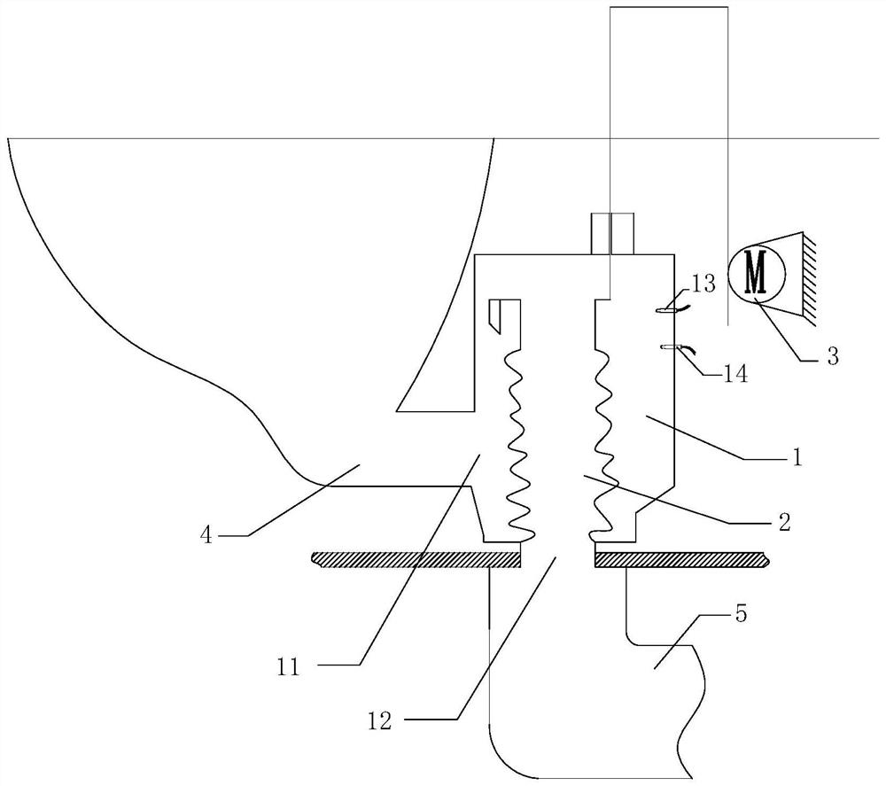
[0034] refer to figure 1 , a toilet sewage structure, comprising: a buffer chamber 1, an on-off valve 2 and a control mechanism 3 for driving the on-off valve 2 up and down; the water inlet 11 of the buffer chamber 1 communicates with the toilet sewage pipe 4, and the outlet of the buffer chamber 1 The water outlet is communicated with the sewage sewer pipe 5 .

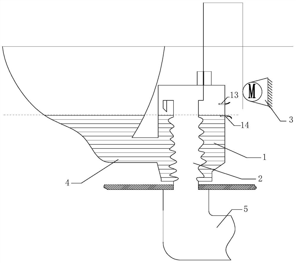
[0035] The lower end of the on-off valve 2 communicates with the sewage and sewage pipeline 5 through the water outlet 12, and the upper end of the on-off valve 2 is provided with a water inlet; the control mechanism 3 controls the on-off valve 2 to move between the highest position and the lowest position, when the control mechanism 3 When the control on-off valve 2 is raised to a high position, the water inlet is higher than the water cover when the water is not flushed, such as figure 2 As shown, this can ensure that the water in the toilet and the buffer chamber 1 will not be discharged from the on-off valve 2, ...

Embodiment 2

[0041] refer to Figure 7-12 The difference between this embodiment and Embodiment 1 is that in this embodiment, the on-off valve has a water stopper 6, and the water stopper is used to open or close the water outlet 12 of the buffer chamber 2.

[0042] The water inlet of the buffer chamber 1 communicates with the toilet sewage pipe 4, the water outlet 12 of the buffer chamber 1 communicates with the sewage sewer pipe 5, and the water stopper 6 is used to open or close the water outlet 12; as Figure 7 shown.

[0043] A liquid level sensor 15 is arranged in the buffer chamber 1, and the position of the liquid level sensor 15 is higher than the water cover when not flushing, such as Figure 8As shown; when the toilet is flushed, the liquid level in the buffer chamber 1 rises, and when the liquid level in the buffer chamber 1 reaches the position where the first liquid level sensor 13 is located, the control mechanism 3 drives the water stopper 6 to open the buffer chamber 1 T...


PUM


Abstract

The invention provides a closestool blowdown structure. The closestool blowdown structure comprises a buffer chamber, an on-off valve and a control mechanism used for driving the on-off valve to be switched between a water seal state and a drainage state. A water inlet of the temporary storage chamber is communicated with a closestool blow-off pipe, and a water outlet of the temporary storage chamber is communicated with a blow-off sewer pipe; the on-off valve is arranged at the water outlet of the buffer chamber and located in the buffer chamber; a first liquid level sensor is arranged in the buffer chamber, when the closestool flushes water, the liquid level in the buffer chamber rises, and when the first liquid level sensor detects a liquid level signal, the control mechanism controls the on-off valve to be switched to a drainage state; and the position of the first liquid level sensor is higher than the water sealing surface when water is not flushed. The invention further provides a closestool, the closestool drainage structure is used, the pipe diameter of the drainage pipe can be increased, an S-shaped bent pipe is omitted, drainage resistance is reduced, and drainage noise is reduced.

Description

technical field [0001] The invention relates to the field of household bathrooms, in particular to a toilet. Background technique [0002] The general energy toilets on the market have long ceramic S-bend pipes, and due to the influence of the ceramic forming process, molds, and ceramic seat height restrictions, the diameter of the pipes generally cannot be enlarged (generally 41-48mm), so the toilet sewage needs to be relatively large. Large potential energy and water volume; this has caused the existing toilet flushing to require a relatively large amount of water, relatively high water pressure, and relatively large noise. Contents of the invention [0003] The main technical problem to be solved by the present invention is to provide a toilet blowdown structure. By increasing the diameter of the blowdown pipe and shortening the length of the blowdown pipe, the resistance of drainage can be reduced; The sewage is discharged after the water level rises, which has the ef...

Claims


Application Information

Patent Timeline
Patent Type & Authority Applications(China)
IPC IPC(8): E03D11/02E03D11/13
CPCE03D11/02E03D11/13
Inventor 涂祥毅吕俊效蔡涛詹庆华路超殷一凡
Owner XIAMEN SOLEX HIGH TECH IND CO LTD
Why Eureka
Try Eureka