
Floating seal assembly

A floating seal and assembly technology, applied in the direction of engine seals, engine components, transmission parts, etc., can solve the problems of reduced compression force, exposure of crawler to soil, sand or silt, other pollutants, and reduced surface pressure. The effect of improving lifespan

Pending Publication Date: 2021-06-11
股份公司摩拓乐
View PDF9 Cites 0 Cited by
  • Summary
  • Abstract
  • Description
  • Claims
  • Application Information

AI Technical Summary

Problems solved by technology

[0004] However, since construction machinery usually works in harsh operating environments, the tracks of construction machinery are frequently exposed to soil, sand or silt, and other pollutants
Therefore, there is the following problem: as foreign matter continues to flow into the gap of the drive mechanism, the O-ring of the floating seal assembly is pressurized, and as the O-ring is pushed under pressure, the compression force decreases, resulting in The surface pressure of the sealing ring (seal ring) drops and oil leakage occurs

Method used


Image

  • Floating seal assembly
  • Floating seal assembly
  • Floating seal assembly

Examples


Embodiment Construction

[0018] Embodiments of the present invention will be described below with reference to the accompanying drawings so that those skilled in the art to which the present invention pertains can easily implement. The present invention can be implemented in various forms and is not limited to the embodiments described here.

[0019] In addition, in several embodiments, the same code|symbol is used for the component which has the same structure, and the 1st embodiment is representatively demonstrated, and only the structure different from 1st embodiment is demonstrated in the remaining embodiment.

[0020] The figures are diagrammatic and not shown to scale. For the accuracy and convenience of the drawings, the relative sizes and ratios of the parts in the drawings are shown in exaggerated or reduced sizes, and any sizes are only exemplary rather than limiting. And the same reference numerals are used for the same structure, element or component shown in two or more figures to denote...


PUM


Abstract

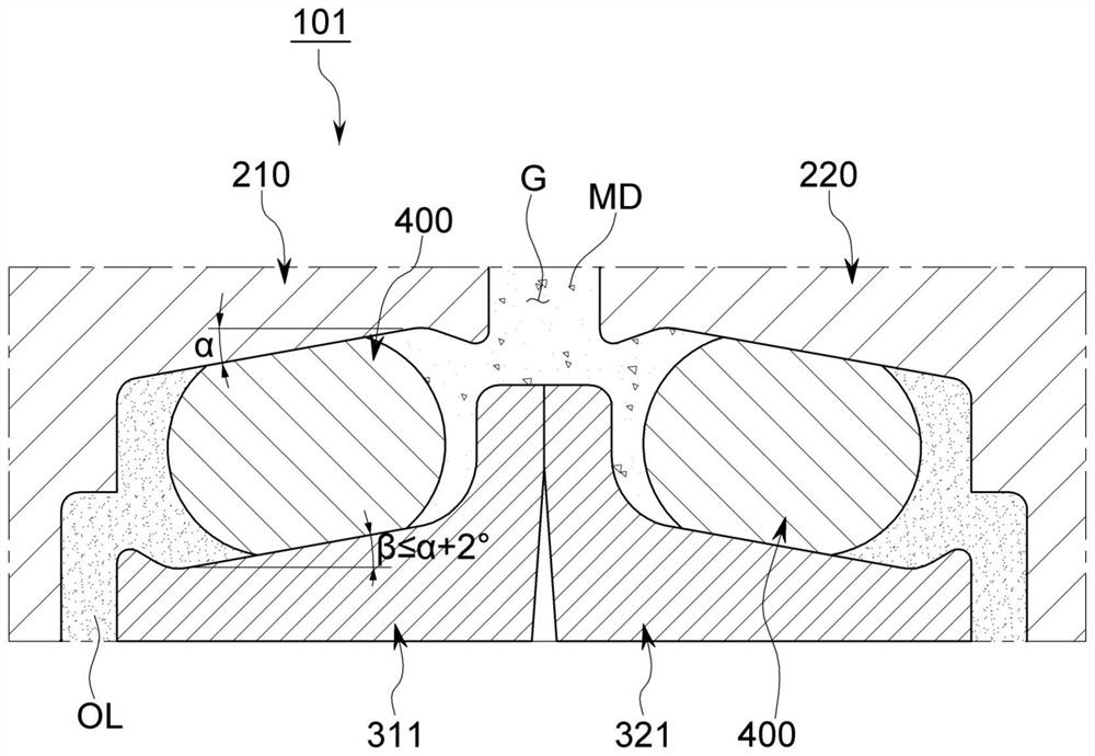
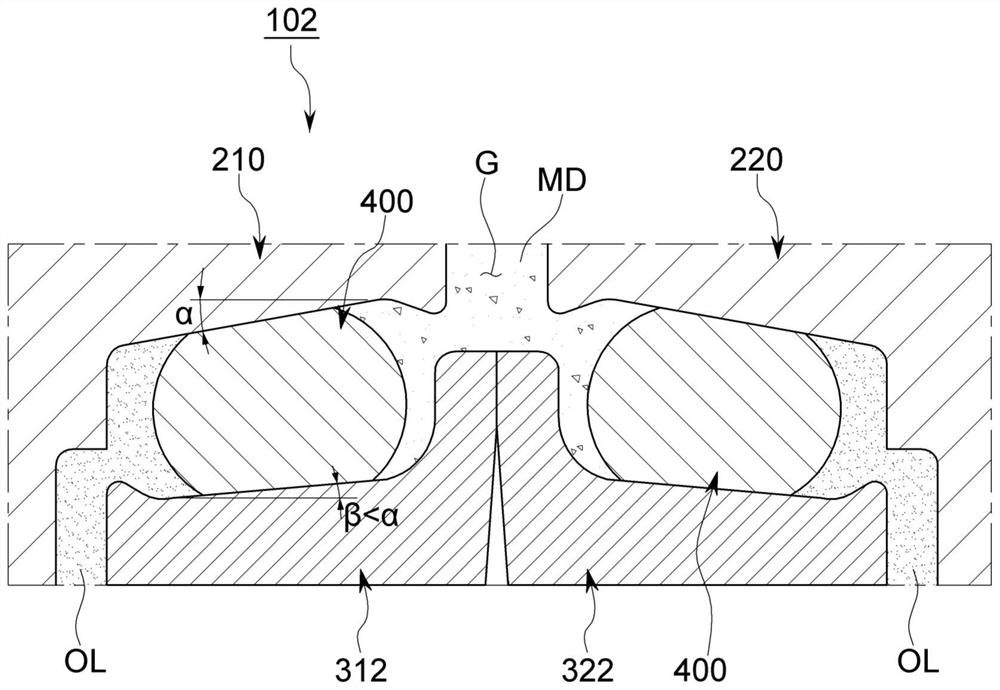
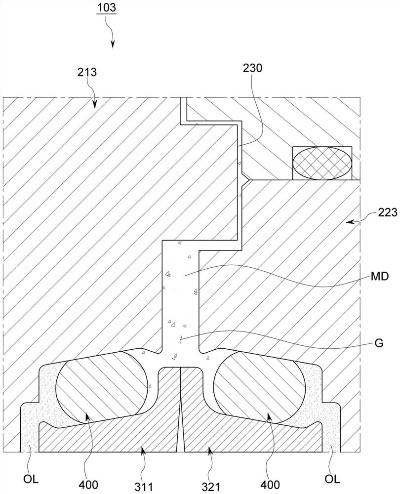
The present invention relates to a floating seal assembly which prevents lubricating oil from flowing out of a gap between a first housing and a second housing and prevents foreign matter from flowing into the gap, at least one of the first housing and the second housing rotating, and the floating seal assembly according to an embodiment of the present invention comprises: a first seal ring which is opposed to the first housing and is provided with a first sealing ring; one side of the second shell protrudes towards a gap between the first shell and the second shell; a second seal ring that faces the second housing, one side of which protrudes toward a gap between the first housing and the second housing and is in contact with one side of the first seal ring; and the O-shaped rings are respectively arranged between the first shell and the first sealing ring and between the second shell and the second sealing ring.

Description

technical field [0001] The present invention relates to a floating seal assembly that prevents lubricating oil from flowing out of a gap between a pair of housings, one of which rotates, and foreign matter from flowing into the gap. Background technique [0002] Construction machinery refers to all machinery used in civil engineering or building construction. In addition, construction machines can be broadly classified into crawler type using crawler belts and wheel type using tires according to the form of the traveling device. [0003] Among them, a crawler-type construction machine uses a driving mechanism such as an idler and a speed reducer to rotate the crawler belt, and lubricating oil is supplied to make such a driving mechanism operate smoothly. In addition, floating seals are used to prevent lubricating oil from leaking from the drive mechanism and foreign materials such as earth, sand, and silt to flow into the drive mechanism. [0004] However, since constructi...

Claims


Application Information

Patent Timeline
IPC IPC(8): F16J15/44F16J15/447F16H57/029B62D55/088B62D55/092
CPCF16J15/441F16J15/4476F16H57/029B62D55/0887B62D55/092F16J15/3232F16J15/447
Inventor 车尚玟金泰勋
Owner 股份公司摩拓乐
Features
  • Generate Ideas
  • Intellectual Property
  • Life Sciences
  • Materials
  • Tech Scout
  • Unparalleled Data Quality
  • Higher Quality Content
  • 60% Fewer Hallucinations
Learn More