Direct-current separation anode plate protection method and device
An anode plate and direct current technology, applied in chemical instruments and methods, electrochemical sludge treatment, dehydration/drying/thickened sludge treatment, etc., can solve the problems of reducing dehydration effect and performance degradation, so as to improve the effect and improve the service life , to avoid the effect of performance degradation of the anode plate
- Summary
- Abstract
- Description
- Claims
- Application Information
AI Technical Summary
Problems solved by technology
Method used
Image

Examples
Embodiment 1
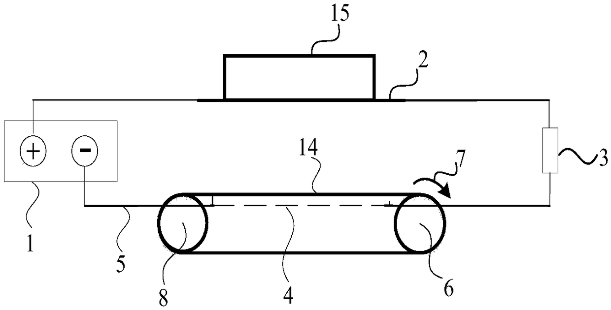
[0025] This embodiment is an embodiment of protecting the anode plate of the electroosmotic dehydration device for excess sludge in a sewage treatment plant. After mechanical press filtration, the remaining sludge has a water content of 82%, and then enters the electroosmosis device, where it is dehydrated under the action of a direct current electric field. The electroosmotic dehydration device adopted is a batch operation mode (such as the anode plate moves up and down, and the sludge moves horizontally, that is, after the sludge enters between the cathode and anode plates, both the cathode and anode plates stop mechanical movement. Dehydration is carried out, and when the required water content (about 60%) is reached, both the anode plate and the cathode are out of contact with the sludge, and the sludge is discharged. At this time, no current flows through the sludge between the cathode and anode plates. use as figure 2 In the system shown, the anode plate 2 moves up an...
Embodiment 2
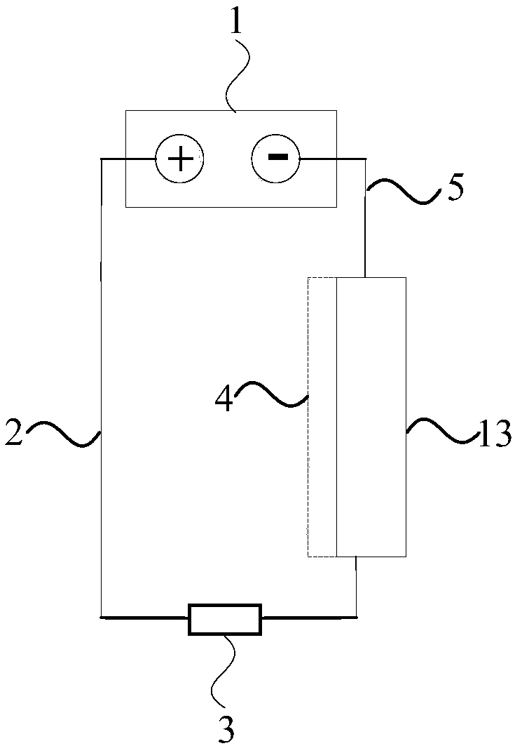
[0028] This embodiment is basically the same as Embodiment 1, and the electric device 3 is a sliding rheostat. The difference is that the electroosmosis device is a plate-and-frame structure in which the anode plate and the cathode are vertically arranged, such as image 3 shown. After the sludge (not shown in the figure) enters between the anode plate 2 and the cathode 4, a DC electric field is applied between the cathode and the anode while pressure is applied through the cathode pressurized fluid space 13 for dehydration. When the electroosmosis reaches the required water content, the anode plate and the cathode are out of contact with the sludge and the sludge is discharged. At this time, no current flows through the sludge between the cathode and anode plates. After the anode plate is out of contact with the sludge, an electric circuit is formed between the anode plate 2 and the cathode 4 through an external power supply 3 and a wire 5 connected to the power supply 1 , a...
Embodiment 3
[0031] This embodiment is basically the same as Embodiment 1, the difference is that when the equipment is overhauled or shut down, press figure 2 In the shown mode, an external power supply is connected between the anode plate and the cathode. There are many production shutdowns such as maintenance, such as more than 2 hours a week, when no external power is connected, the dehydration efficiency of the anode plate will drop significantly after 3.5 months of use, and the method for protecting the anode plate of the present invention will be in 1.5 years. began to decline significantly. The life of the anode plate is significantly extended. And the protective current density on the anode plate is only equivalent to 1 / 20 of the lowest value in the later stage of electroosmosis.
PUM
 Abstract
Description
Claims
Application Information
 - Generate Ideas
- Intellectual Property
- Life Sciences
- Materials
- Tech Scout
- Unparalleled Data Quality
- Higher Quality Content
- 60% Fewer Hallucinations
Browse by: Latest US Patents, China's latest patents, Technical Efficacy Thesaurus, Application Domain, Technology Topic, Popular Technical Reports.
© 2025 PatSnap. All rights reserved.Legal|Privacy policy|Modern Slavery Act Transparency Statement|Sitemap|About US| Contact US: help@patsnap.com