an oil pipeline
A technology for oil pipelines and pipelines, applied in pipeline heating/cooling, pipe components, pipes/pipe joints/fittings, etc., can solve problems such as single structure, achieve the effects of enhancing friction efficiency, increasing temperature, and reducing adhesion
- Summary
- Abstract
- Description
- Claims
- Application Information
AI Technical Summary
Problems solved by technology
Method used
Image
Examples
Embodiment 1
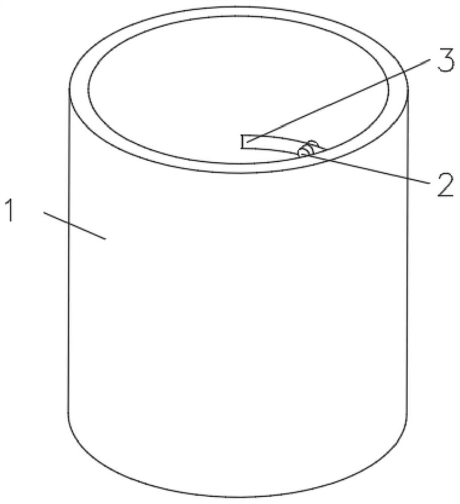
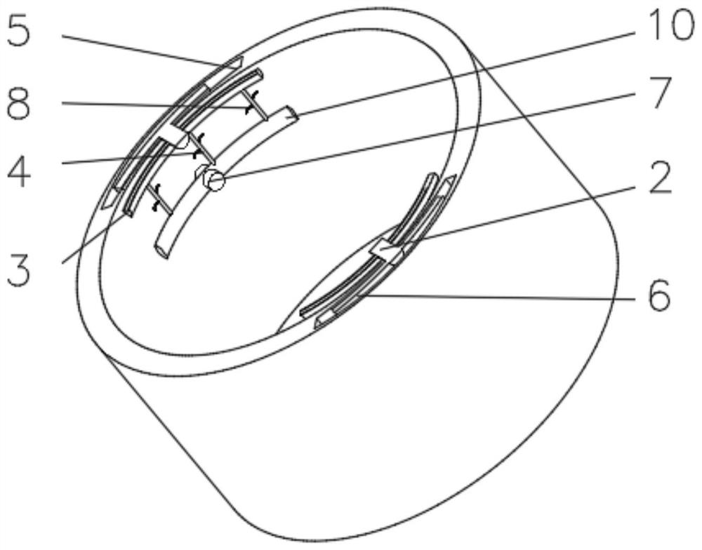
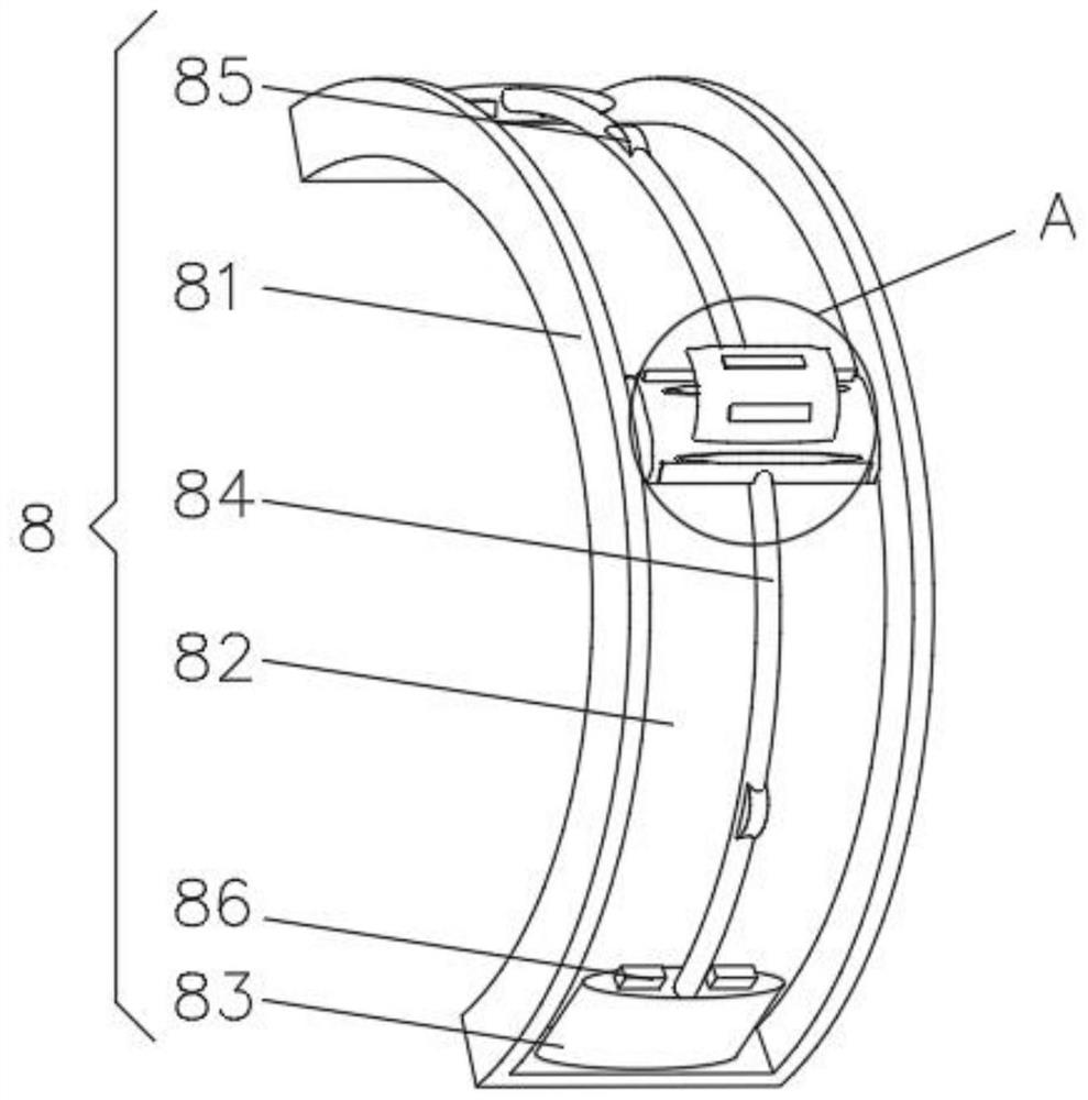
[0030] see Figure 1-3 , the present invention provides a technical solution: an oil pipeline, comprising a pipeline 1, the inner wall of the pipeline 1 is fixedly connected with a fixed column 2, the end of the fixed column 2 away from the pipeline 1 is connected with an arc-shaped plate 3, and the arc-shaped plate 3 is away from the fixed An elastic telescopic rod 4 is evenly installed on one side of the column 2, an arc-shaped groove 5 is symmetrically opened inside the pipe 1 near the fixed column 2, and the end of the fixed column 2 away from the arc-shaped plate 3 extends through the pipe 1 to the arc-shaped groove 5. Inside, the end of the fixed column 2 close to the arc groove 5 is fixedly connected with an arc rubber block 6, the inner wall of the pipe 1 is symmetrically installed with a limit column 7 at the position close to the fixed column 2, and a friction device is symmetrically installed on one side of the elastic telescopic rod 4 8. A contact device 9 is insta...
Embodiment 2
[0035] see Figure 1-4 , the present invention provides a technical solution: on the basis of the first embodiment, the contact device 9 includes a sliding block 91, the sliding block 91 is slidably connected with the sliding rod 84, and a second magnet block 92 is symmetrically installed on one side of the sliding block 91, A rubber block 93 is symmetrically mounted on one side of the sliding block 91 .
[0036] An arc-shaped elastic plate 94 is fixedly connected to the side of the sliding block 91 close to the rubber block 93 , and a rubber soft block 95 is installed on the side of the arc-shaped elastic plate 94 away from the sliding block 91 .
[0037] When in use, when the sliding block 91 slides along the sliding rod 84, it is close to the first magnet block 86. Since the second magnet block 92 and the first magnet block 86 are magnets of the same sex, the first magnet block 86 turns the second magnet block 86 into contact with the second magnet block 86. The block 92 i...
Embodiment 3
[0039] see Figure 1-5 , the present invention provides a technical solution: on the basis of the second embodiment, a shaking device 10 is installed at one end of the limiting column 7 away from the pipeline 1, and the shaking device 10 includes a device frame 101, and a wave groove is opened on one side of the device frame 101 102, a groove 103 is opened inside the wave groove 102.
[0040] A push plate 104 is symmetrically installed inside the groove 103 , and a spring 105 is fixedly connected between the push plates 104 .
[0041]During use, when the oil flows in the pipe and contacts the device frame 101, when the push plate 104 is subjected to the flow, the gravity of the oil squeezes the spring 105 on one side so that the push plate 104 on the other side shakes. The gravitational compression spring of the oil drives the push plate to shake, which effectively improves the turbulence of the flowing oil and reduces the adhesion.
PUM
 Abstract
Description
Claims
Application Information
 - R&D
- Intellectual Property
- Life Sciences
- Materials
- Tech Scout
- Unparalleled Data Quality
- Higher Quality Content
- 60% Fewer Hallucinations
Browse by: Latest US Patents, China's latest patents, Technical Efficacy Thesaurus, Application Domain, Technology Topic, Popular Technical Reports.
© 2025 PatSnap. All rights reserved.Legal|Privacy policy|Modern Slavery Act Transparency Statement|Sitemap|About US| Contact US: help@patsnap.com


