
Printing head, printing method and device using same

A technology of print head and equipment, applied in the field of print head

Inactive Publication Date: 2003-12-03
CANON KK
View PDF4 Cites 0 Cited by
  • Summary
  • Abstract
  • Description
  • Claims
  • Application Information

AI Technical Summary

Problems solved by technology

However, in addition to the aforementioned problems, there are structural changes in the opening area and changes in the film thickness of the protective film provided on the heating element 901

Method used


Image

  • Printing head, printing method and device using same
  • Printing head, printing method and device using same
  • Printing head, printing method and device using same

Examples


Embodiment Construction

[0063] The preferred embodiments of the present invention will be described in detail below in conjunction with the accompanying drawings.

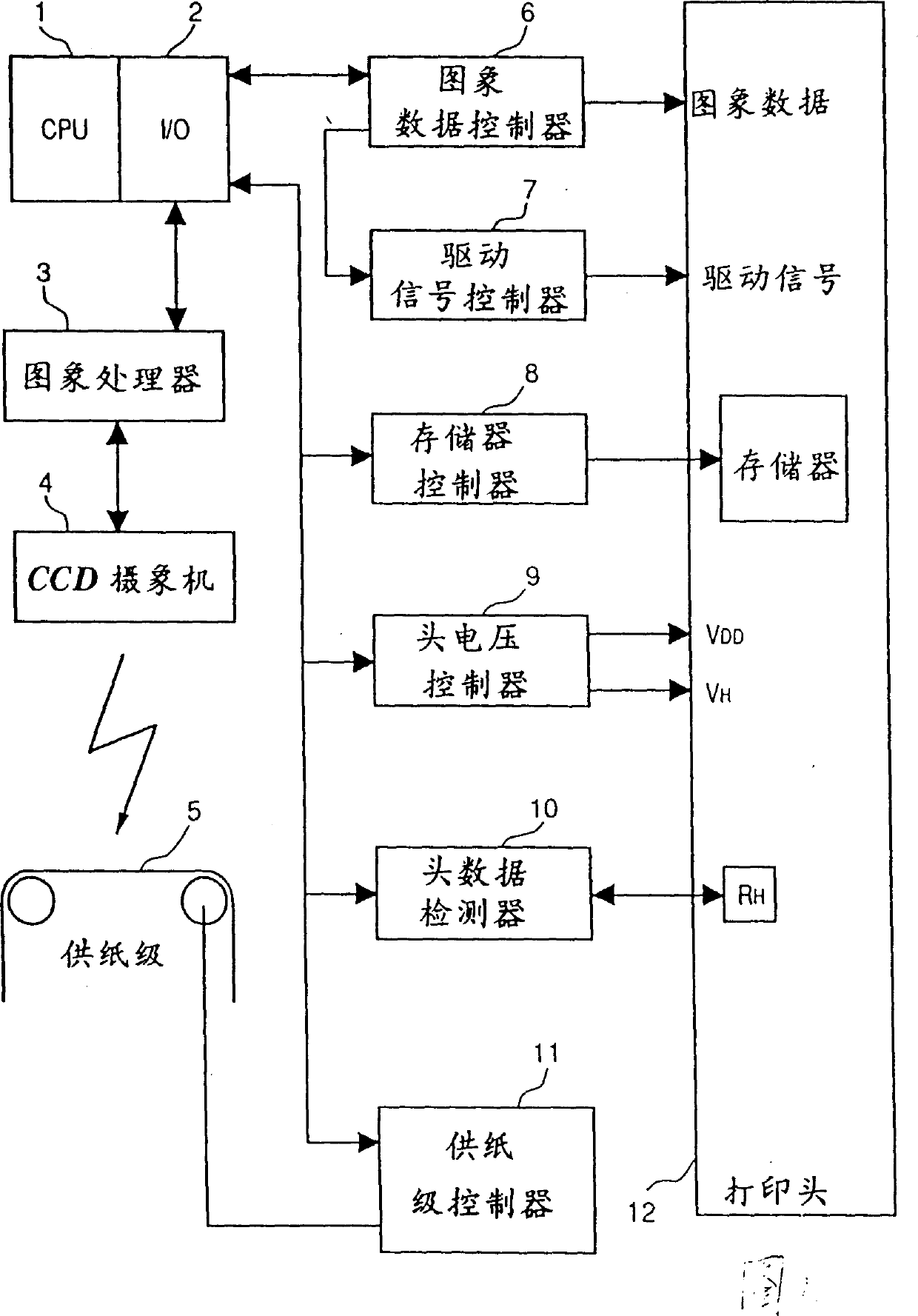
[0064] FIG. 1 is a block diagram showing the configuration of a head correction apparatus for determining correction data of a print head 12 according to a first embodiment of the present invention.

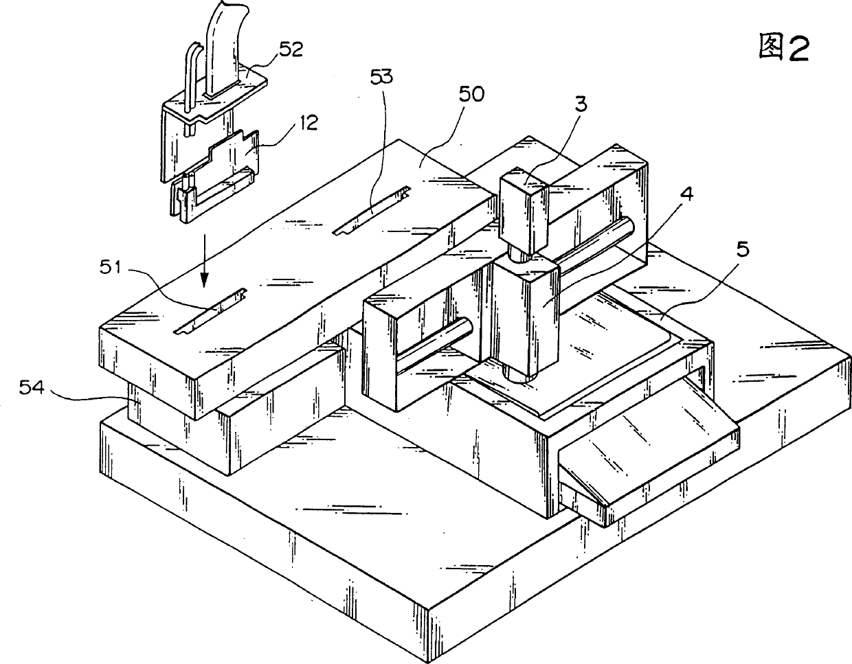
[0065] In FIG. 1, a CPU 1 which controls the entire correction apparatus manages various controllers which will be described later. The I / O interface 2 interfaces the CPU 1 with the respective parts of the device. The image processor 3 reads the printed dot pattern on the recording medium placed on the paper supply stage 5 with the CCD camera 4 and obtains pixels corresponding to the diameter and density of the printed dots. When the dot data corresponding to all the printing elements (nozzles) of the print head 12 are sent from the image processor 3 to the CPU 1, the CPU 1 operates on the dot data in accordance with the driving signal for ...


PUM


Abstract

A printing head has a plurality of heater boards, each of which includes a shift register to which printing data and selection data for selecting preheating pulse signals are applied as inputs, a latch circuit for latching the printing data, a selection-data latch circuit for latching the selection data, a selection circuit for selecting any one of a plurality of preheating pulse signals inputted in accordance with the latched selection data, and a plurality of heating resistors driven by the printing data or preheating pulse signals. Correction data, obtained by a head correcting apparatus, for performing printing at an average density by correcting the characteristics of each heater board is stored in a memory of the printing head. A printing apparatus decides the selection data in accordance with the correction data and sets the selection data in the selection-data latch circuit.

Description

technical field [0001] The present invention relates to a printhead with a plurality of printing elements, a printing method and apparatus using the printhead, and a method and apparatus for calibrating the printhead. Background technique [0002] A printing apparatus such as a printer, copier or facsimile prints an image including dot patterns according to image information on a printing medium such as paper, thin plastic sheet or cloth. Of these printing apparatuses, particularly attractive due to low cost, are printing apparatuses employing print heads that rely on the inkjet method, the thermal printing method, or the LED method, etc.—a plurality of printing elements corresponding to dots in these methods arranged on a base. [0003] In a print head in which printing elements such as heating resistors or nozzles are arranged in a certain printing width, the printing elements can be fabricated by a method similar to that of semiconductors. Therefore, a transition from a...

Claims


Application Information

Patent Timeline
Patent Type & Authority Patents(China)
IPC IPC(8): B41J2/05B41J2/155B41J29/393
CPCB41J2/04506B41J2/155B41J2/0458B41J29/393B41J2202/17B41J2/04543B41J2/04565B41J2/04563B41J2/04541B41J2202/21B41J2202/20B41J2/04588B41J2/04591B41J2/04598B41J2/01G06F15/00
Inventor 今仲良行稻页正树池田雅実小泉宽折笠刚古川达生樫野俊雄岸田秀昭刈田诚一郎小山修司寺井晴彦林崎公之片尾周一后藤显小俣好一丸博之泉田昌明上山雄次小野敬之
Owner CANON KK
Learn More