Cutting tool with preloaded springs and assembling method thereof

A technology of pre-tightening springs and cutting tools, which is applied to components with teeth, gear cutting machines, manufacturing tools, etc. It can solve the problems of inconvenient assembly, difficulty in achieving the pre-tightening effect, uneven force on the upper and lower sides of the blade, and achieve easy assembly , simple structure, and the effect of improving the efficiency of knife loading

Pending Publication Date: 2021-06-15
HUNAN ZDCY (ZHONGDA CHUANG YUAN) CNC EQUIP CO LTD
View PDF12 Cites 1 Cited by
  • Summary
  • Abstract
  • Description
  • Claims
  • Application Information

AI Technical Summary

Problems solved by technology

[0009] However, the structure of this pre-tightening and clamping milling cutter bar has many parts, at least three parts of spring, steel ball and retaining ring are needed. If the number of milling cutter bars is 24, a total of 24 springs, 24 steel balls and 24 retaining rings, compared with traditional cutting tools, there will be 72 more scattered parts, which is very inconvenient to assemble. Moreover, because the spring hole needs to have a certain depth, in order to avoid the locking screw, on the pressing block It can only be in the upper position, which will lead to uneven force on the blade in the pre-tightened state, making it difficult to achieve the ideal pre-tightening effect

Method used


Image

  • Cutting tool with preloaded springs and assembling method thereof
  • Cutting tool with preloaded springs and assembling method thereof
  • Cutting tool with preloaded springs and assembling method thereof

Examples


Embodiment Construction

[0034] In order to enable those skilled in the art to better understand the solution of the present invention, the present invention will be further described in detail below in conjunction with the accompanying drawings and specific embodiments.

[0035] In this article, terms such as "upper, lower, left, and right" are established based on the positional relationship shown in the drawings. Depending on the drawings, the corresponding positional relationship may also change accordingly. For the part of the definition, the direction of the literal definition is preferred, so it cannot be understood as an absolute limitation on the scope of protection; moreover, relative terms such as "first" and "second" are only used to connect a Another component having the same name does not necessarily require or imply any such actual relationship or order between these components.

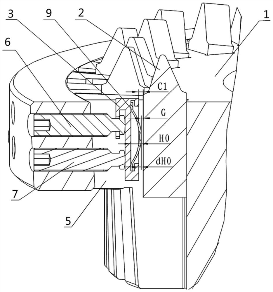
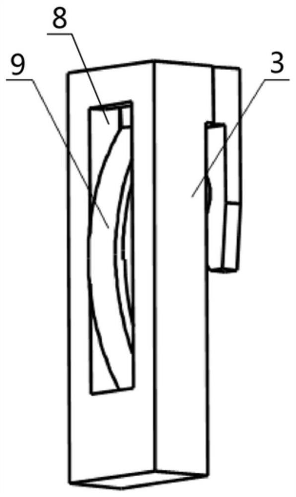
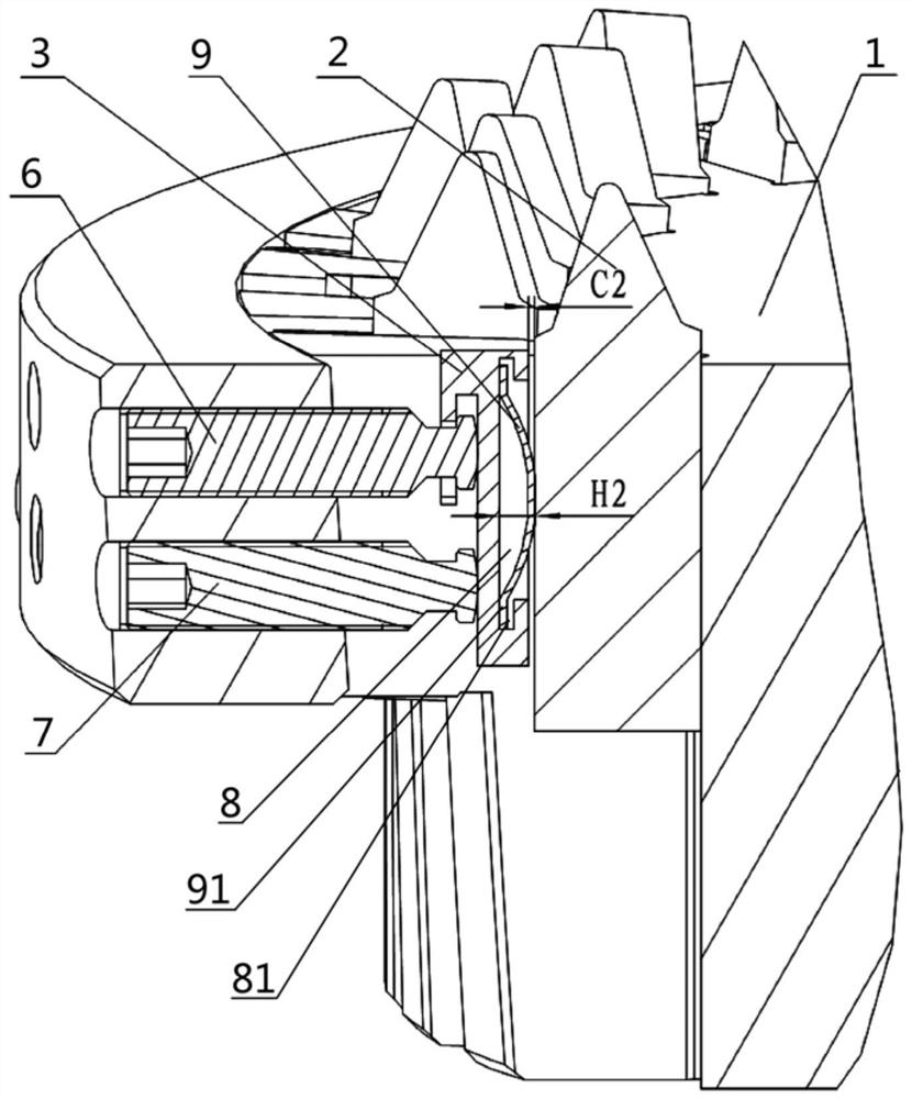
[0036] Please refer to figure 1 , figure 2 , figure 1 It is a cross-sectional view of a cutting tool wi...


PUM


Abstract

The invention discloses a cutting tool with preloaded springs and an assembling method thereof. The cutting tool comprises a tool body, wherein tool grooves are formed in the tool body, threaded through holes are formed between the outer edge of the tool body and the tool grooves, locking screws are arranged in the threaded through holes, pressing blocks are arranged between the locking screws and blades, a spring groove is formed in the inner side face of each pressing block, the preloaded springs are arranged in the spring grooves, the preloaded springs are each provided with a pressure applying portion which makes contact with the pressed face of a blade in the inserting and withdrawing directions in a smooth transition mode, and in a preloaded state, the pressure applying portions of the preloaded springs are higher than the inner side faces of the pressing blocks and are in contact with the pressed surface of the blade. According to the cutting tool, when the tool is assembled, the blade can enter a preloaded state after being inserted into the tool grooves, the blade can be continuously and smoothly inserted into and withdrawn from the tool grooves, adjustment is easy, the number of parts is small, and it can be guaranteed that the blade is in a reasonable stress state.

Description

technical field [0001] The invention relates to the technical field of gear cutters, in particular to a blade-type assembled cutter for cutting gears. The invention also relates to a method of assembling the tool. Background technique [0002] Gear cutting tools basically rotate around the tool axis when cutting, and can be simply divided into integral tools and assembled tools. Assembled knives typically have a tool body that is arranged with one or more pockets to accommodate blades, each insert being positioned in the pocket and locked in place with one or more locking screws and pressure blocks. in the knife pocket. [0003] The blade-type assembled tool requires that on the basis that the cutting edge of the blade reaches a grinding accuracy within a certain tolerance range, the cutting edge of the blade with the same name after assembly must also be adjusted and controlled within a certain tolerance range in the radial and axial directions. The tightening screw and ...

Claims


Application Information

Patent Timeline
Patent Type & Authority Applications(China)
IPC IPC(8): B23F21/00B23F23/12
CPCB23F21/00B23F23/1206
Inventor 杨洪成李国胜岳明强王艳
Owner HUNAN ZDCY (ZHONGDA CHUANG YUAN) CNC EQUIP CO LTD
Why Eureka
Try Eureka