
Active tilting device

An active and reducer technology, applied in the field of rail transit, can solve the problems of large moment resistance of the anti-roll torsion bar, hinder the tilting of the car body, and large actuators, and achieve small tilting resistance, small structural changes, and compatibility. good effect

Inactive Publication Date: 2021-06-15
CRRC QINGDAO SIFANG ROLLING STOCK RES INST
View PDF12 Cites 1 Cited by
  • Summary
  • Abstract
  • Description
  • Claims
  • Application Information

AI Technical Summary

Problems solved by technology

[0005] For a two-point supported vehicle, the anti-roll torsion bar has a relatively high rigidity. If other tilting methods are used, the anti-roll torsion bar will generate a large moment resistance, hindering the vehicle body from tilting, causing the actuator to be larger or even exceed the The maximum limit value of bearing capacity and strength of other components

Method used


Image

  • Active tilting device
  • Active tilting device
  • Active tilting device

Examples


Embodiment Construction

[0035] The technical solutions of the present invention will be described in further detail below with reference to the accompanying drawings and embodiments.

[0036] The embodiment of the present invention provides an active tilting device, which is especially suitable for a bogie with a two-point support method for the car body, a small span of two air springs, and a large roll rigidity of an anti-roll torsion bar.

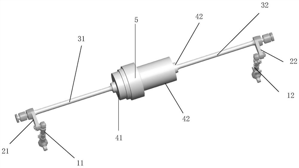
[0037] figure 2 It is a schematic structural diagram of an active tilting device provided in Embodiment 1 of the present invention, image 3 A perspective view of an active tilting device provided in Embodiment 1 of the present invention; combined figure 2 , image 3 As shown, the active tilting device provided by the present invention includes: a first adjustable link 11, a second adjustable link 12, a first torsion arm 21, a second torsion arm 22, a first torsion bar 31, a second torsion bar Rod 32, first flange 41, second flange 42, third flange 43, red...


PUM


Abstract

The invention discloses an active tilting device which comprises a first adjustable connecting rod, a second adjustable connecting rod, a first torsion arm, a second torsion arm, a first torsion bar, a second torsion bar, a first flange, a second flange, a third flange, a speed reducer, a motor and an outer sleeve support. The input end of the speed reducer is connected with the motor through the third flange, the outer sleeve support is connected to the shell of the speed reducer, and the motor is arranged in the outer sleeve support. The first flange is connected to the output end of the speed reducer, one end of the first torsion bar is in interference fit with the first flange, and the other end is in interference fit with the first torsion arm; the first adjustable connecting rod is in spherical hinge connection with the first torsion arm; the second flange is fixedly connected with the outer sleeve support, one end of the second torsion bar is in interference fit with the second flange, and the other end is in interference fit with the second torsion arm; and the second adjustable connecting rod is in spherical hinge connection with the second torsion arm.

Description

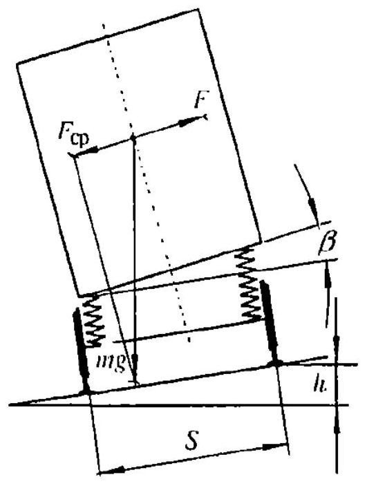
technical field [0001] The invention relates to the technical field of rail transportation, in particular to an active tilting device. Background technique [0002] High speed and comfort are the development trend of rail vehicles. However, due to the limitation of line conditions, such as the large number of curve segments and many small radius curves, simply increasing the running speed of the vehicle will increase the unbalanced centrifugal force of the vehicle during the turning process, which will affect passengers. The comfort and the safety and stability of the vehicle. Considering the high cost of building high-speed railways, high maintenance costs, and high technical requirements, it is expected that the vehicles on the existing lines will be transformed so as to achieve the purpose of increasing the running speed of the vehicles. [0003] Tilting train is an effective technical measure to increase the speed of existing lines. The working principle is as follows: ...

Claims


Application Information

Patent Timeline
Patent Type & Authority Applications(China)
IPC IPC(8): B61F5/38B61F5/24
CPCB61F5/38B61F5/24
Inventor 林佳志巩永强谢国贞宋红光
Owner CRRC QINGDAO SIFANG ROLLING STOCK RES INST
Learn More