Capacity coupling type automatic wireless charging system and charging method for electric automobile

A technology for electric vehicles and wireless charging, applied in the direction of electric vehicle charging technology, electric vehicles, charging stations, etc., can solve the problems of safety hazards, reduce the experience and popularity of wireless charging, and heavy weight

Active Publication Date: 2019-10-01
BEIJING INVISPOWER TECH CO LTD
View PDF10 Cites 10 Cited by
  • Summary
  • Abstract
  • Description
  • Claims
  • Application Information

AI Technical Summary

Problems solved by technology

[0004] ① It is necessary to use metal Litz wire and ferrite materials to make the transmitting and receiving coils, resulting in large volume and heavy weight of the coils, which also increases the investment cost;
[0005] ②The installation and burial of the transmitting coil requires certain civil construction for the parking space, and the installation of the receiving coil requires the modification of the electric vehicle, and even generally requires the redesign of the entire vehicle, and the installation of the receiving coil also increases the load of the vehicle;
[0006] ③In the process of wireless charging, high-power transmission may produce some magnetic field leakage and electromagnetic interference. If there is a metal foreign object that cannot be identified in the transmission magnetic field, the temperature of the foreign object will increase due to the eddy current effect, and even ignite the flammable object to cause a fire. The existing technology still has some potential safety hazards that need to be overcome. Electromagnetic leakage will also pollute the ecological environment and have adverse effects on people's health.
[0008] Due to the constraints of the national regulations on the safety control limits of the electromagnetic environment, the magnetic field strength sent by the electric vehicle wireless charging coil is very small, and the magnetic field signal generated by the closed coil such as the transmitting coil increases rapidly with the distance. Attenuation (inversely proportional to the cube of the distance) is also susceptible to the influence of magnetic substances in the site or the surrounding environment, such as interference from metal objects and materials or other parking vehicles, etc. The detection distance of this method is only near the source of the magnetic field Obviously, when the reliable position detection data is obtained, the driver or the parking system does not have sufficient operating space and reaction time to adjust the vehicle route, which puts high demands on the operator or the parking system, even if In this way, the alignment of the coils cannot be completed correctly, which greatly reduces the experience and popularity of wireless charging
For capacitively coupled wireless charging using small-sized plates, there is no effective way to achieve alignment between the transmitting and receiving plates in existing solutions

Method used


Image

  • Capacity coupling type automatic wireless charging system and charging method for electric automobile
  • Capacity coupling type automatic wireless charging system and charging method for electric automobile
  • Capacity coupling type automatic wireless charging system and charging method for electric automobile

Examples


Embodiment Construction

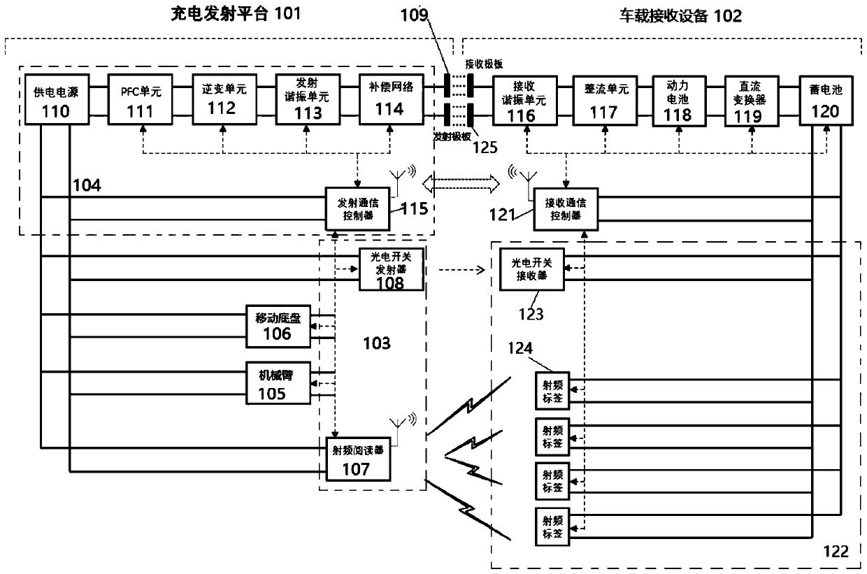
[0061] Below, refer to the attached Figure 1 to Figure 4 As shown, the capacitively coupled electric vehicle automatic wireless charging system includes: a charging transmitting platform 101 and a vehicle receiving device 102;

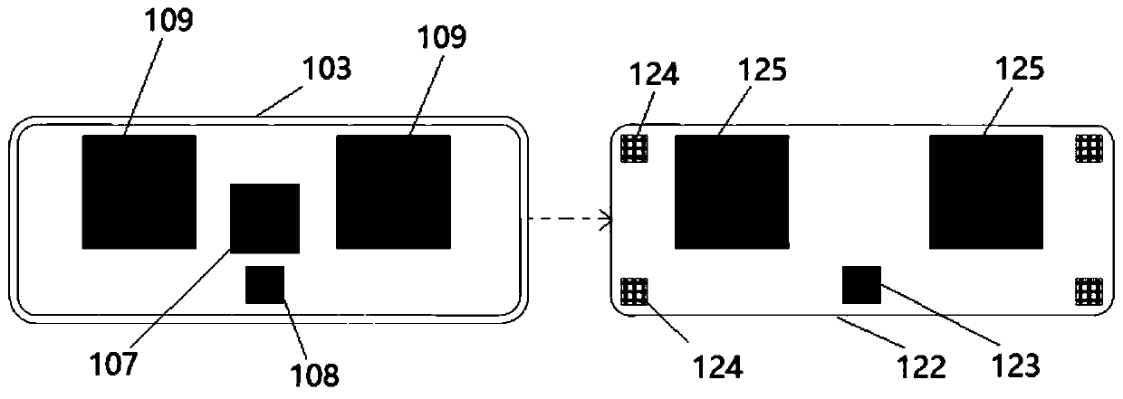
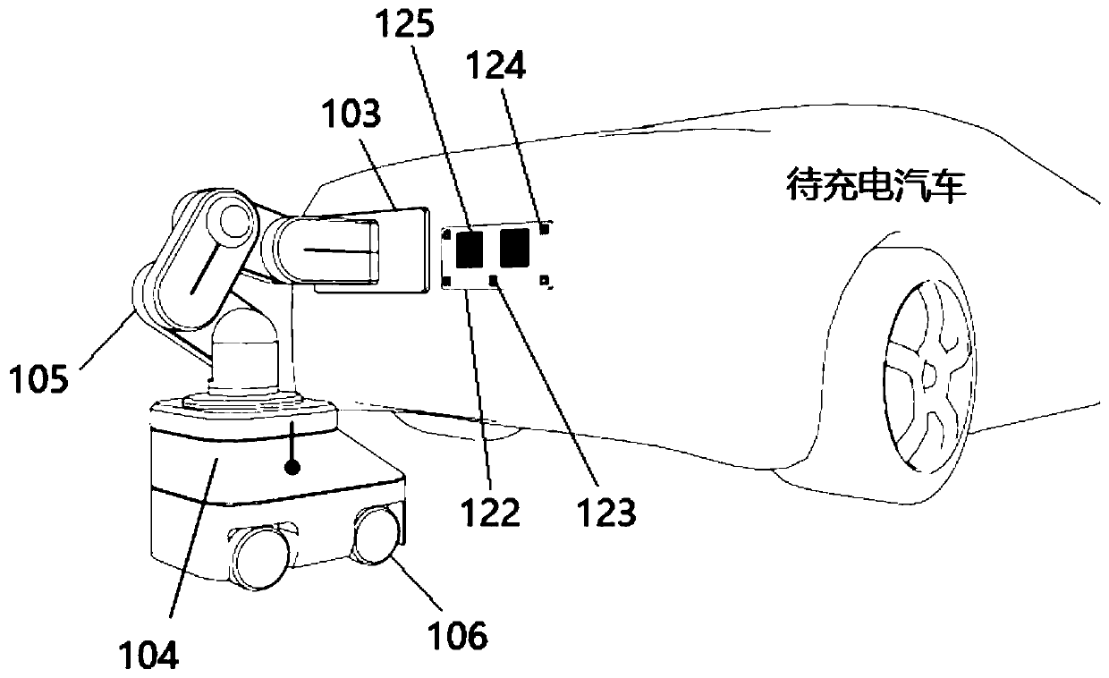
[0062] Further, the charging launch platform 101 includes: a launch unit 103, a launch power supply cabinet 104, a mechanical arm 105 and a mobile chassis 106; the end of the mechanical arm 105 is installed above the launch power supply cabinet 104; the launch power supply The cabinet 104 is installed above the mobile chassis 106; the launch unit 103 is installed on the front end of the mechanical arm 105, and the center position of the launch unit 103 is equipped with a radio frequency reader 107, a photoelectric switch transmitter 108 and two emitter plate 109;

[0063] As an example, the transmitting power supply cabinet 104 includes: an outer casing, and a power supply 110, a PFC unit 111, an inverter unit 112, a transmitting resonance unit 113, ...


PUM


Abstract

The invention discloses a capacity coupling type automatic wireless charging system and charging method for an electric automobile. The system comprises a charging transmitting platform and on-board receiving equipment. The charging transmitting platform comprises a transmitting unit, a transmitting power cabinet, a mechanical arm and a moving chassis. The tail end of the mechanical arm is mountedon the upper portion of the transmitting power cabinet. The transmitting power cabinet is mounted on the upper portion of the moving chassis. The transmitting unit is mounted at the front end of themechanical arm. A radio-frequency reader, an optoelectronic switch transmitter and two transmitting pole plates are mounted at the center position of the transmitting unit. Alignment between couplingmechanisms at the transmitting end and the receiving end does not need to be achieved through manual driving or automatic parking, the to-be-charged electric automobile only needs to be parked at thedesignated parking position, the charging transmitting platform and the multi-freedom-degree mechanical arm carried by the charging transmitting platform can complete the above action, and therefore the problems that during electric automobile wireless charging, coils need to be aligned and operation is inconvenience are solved; and system safety running can be guaranteed, and high conveying efficiency can also be obtained.

Description

technical field [0001] The invention relates to the technical field of electric vehicle wireless charging, in particular to a capacitively coupled electric vehicle automatic wireless charging system and a charging method. Background technique [0002] The non-contact wireless charging technology has the characteristics of automation, convenience, and safety. The use of wireless charging can solve some problems caused by the contact wired charging method of electric vehicles; Apply high-frequency alternating current to the transmitting coil installed on the ground to generate an alternating magnetic field. Under the action of the high-frequency alternating magnetic field, the receiving coil installed on the electric vehicle induces a high-frequency alternating current, which is then converted into direct current by a rectifier for transmission. Charging to the car battery; the magnetic field coupling wireless charging technology has the advantages of large transmission power,...

Claims


Application Information

Patent Timeline
Patent Type & Authority Applications(China)
IPC IPC(8): B60L53/126H02J50/05H02J50/70
CPCB60L53/126H02J50/05H02J50/70Y02T90/16Y02T10/72Y02T10/70Y02T90/14Y02T10/7072
Inventor 王哲陆钧贺凡波葛俊杰马俊超
Owner BEIJING INVISPOWER TECH CO LTD
Why Eureka
Try Eureka