
River power generation system

A power generation system, river technology, applied in hydropower, control system, engine components, etc., can solve the problems of generator power supply line damage, fast water flow, small potential energy difference, etc., and achieve the effect of preventing too fast transfer

Inactive Publication Date: 2021-06-15
冯佳旋
View PDF9 Cites 0 Cited by
  • Summary
  • Abstract
  • Description
  • Claims
  • Application Information

AI Technical Summary

Problems solved by technology

[0003] However, building dams can make use of the potential energy difference to generate electricity, but building dams will also bring about many social problems, and in many gentle water basins, the potential energy difference is small, and it is impossible to build dams everywhere to use water energy, so How to use the water flow in a relatively flat area has become a goal of exploration. At present, in the process of power generation of existing river power generation devices, some factors often cause the water flow to be too fast, which leads to the high speed of the main shaft of the generator, which in turn leads to power generation. The output voltage of the machine is too high, and the high output voltage is easy to cause damage to the generator and the power supply line (power supply equipment) connected to it. work in the rev range, but this is far from enough, there is room for refinement and improvement

Method used


Image

  • River power generation system
  • River power generation system
  • River power generation system

Examples


Embodiment 1

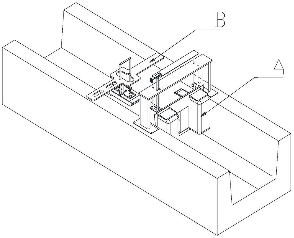
[0033] see Figure 1-Figure 11 , The river power generation system of the present invention includes a water blocking device A arranged in the upstream of the river and a power generation device B arranged in the downstream of the river.

[0034] (1), power generation device A

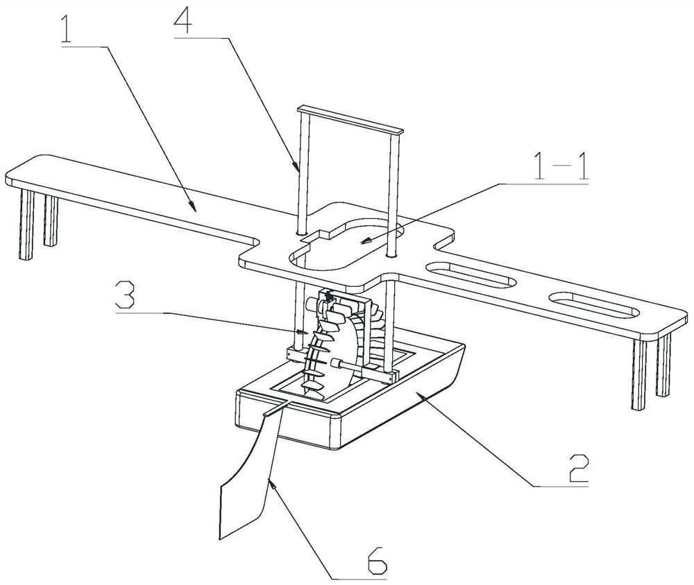
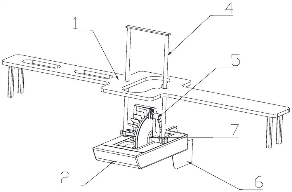
[0035] see Figure 1-Figure 11 , the power generation device straddles the first frame 1 on both sides of the river, the first suspension frame 2 arranged below the first frame 1 , and the power generation module 3 arranged on the first suspension frame 2 .

[0036] see Figure 1-Figure 11, the first suspension frame 2 is made of foam material, and is installed on the first frame 1 through the first vertical guide mechanism 4, and the first frame 1 is in the second position with the power generation module 3 An avoidance groove 1-1; the first vertical guide mechanism 4 is two groups, and each group of first vertical guide mechanism 4 includes a guide hole arranged on the first frame 1 and a guide ho...

Embodiment 2

[0053] see Figure 12 The difference between this embodiment and Embodiment 1 is that the water blocking device includes a second frame 11, a second suspension frame 12, and a water blocking mechanism arranged on the second suspension frame 12, wherein the water blocking device The water mechanism includes a first baffle plate 13, a second baffle plate 14, and a water baffle for driving the first baffle plate 13 and the second baffle plate 14 to move toward each other or reversely to open or close the water inlet. Drive mechanism, wherein, the second frame 11 spans both sides of the river; the second suspension frame 12 is installed on both sides of the river, and is located on the inner side of the river, the first baffle plate 13 and The second baffle 14 is located on both sides of the river, and is respectively rotatably connected to the second suspension frame 12; so that the first baffle 13 and the second baffle 14 can rotate in the vertical direction, thereby controlling...


PUM


Abstract

The invention discloses a river power generation system. The river power generation system comprises a water retaining device and a power generation device, wherein the power generation device comprises a first rack, a first suspension frame and a power generation module; the power generation module comprises a bracket, a power generator and a power generation driving mechanism; a power generation wheel set is rotationally connected with the bracket through a rotating shaft.; the power generation wheel set is connected with a main shaft of the power generator through a synchronous transmission mechanism; the power generation module further comprises a friction braking mechanism; the water retaining device comprises a second rack, a second suspension frame and a water retaining mechanism, and a water inlet is formed in the second suspension frame; and the water retaining mechanism comprises a first baffle, a second baffle and a water retaining driving mechanism. According to the river power generation system, the rotating speed of the river power generation system can be adjusted in a self-adaptive mode according to the flow or the flow speed of a river, so that it is guaranteed that the river power generation system works within a proper rotating speed range, and the situation that the river power generation system and a power supply line or power supply equipment connected with the river power generation system are damaged due to overhigh output voltage of the river power generation system is prevented.

Description

technical field [0001] The invention relates to a power generation device, in particular to a river power generation system. Background technique [0002] Hydropower is a renewable, energy-free, green and clean energy that does not produce carbon dioxide and other environmental pollution, so it is strongly advocated by the state. Traditional hydroelectric power generation is to use the drop of water to impact the blades of the water turbine to drive the generator to generate electricity, and convert the potential energy into electrical energy. Its technical characteristics are closely related to water flow and water drop. The greater the water flow, the greater the water drop, and the greater the amount of electricity that can be generated. In the existing technology and practice, in order to achieve large water volume and large drop, water conservancy dams are usually built to intercept the water. On this basis, hydroelectric power generation facilities are built, and hig...

Claims


Application Information

Patent Timeline
Patent Type & Authority Applications(China)
IPC IPC(8): F03B13/00F03B15/00F03B15/04
CPCF03B13/00F03B15/00F03B15/04F05B2270/1011F05B2260/902F05B2220/706Y02E10/20
Inventor 冯佳旋
Owner 冯佳旋
Learn More