Spiral blade unimpeded type vertical-axis wind turbine wind wheel

A helical, generator technology, applied in wind turbines, wind turbines at right angles to the wind direction, wind turbine combinations, etc. High utilization rate, small rotation space, and no noise

Pending Publication Date: 2021-06-15
申国平
View PDF1 Cites 0 Cited by
  • Summary
  • Abstract
  • Description
  • Claims
  • Application Information

AI Technical Summary

Problems solved by technology

[0002] Wind energy is a clean and renewable energy source. Wind power generation has the advantages of no fuel, no land occupation, no pollution, and low operating costs. The industrial development prospect is very broad; the existing wind power generator components mainly include towers, Wind rotor, pitch system, gearbox, generator, converter, control system, etc.; the wind blade in the wind rotor is the main component for receiving wind energy, and it is also one of the most critical basic components in wind power generation. The wind rotor and its The scientific design, reliable quality, and superior performance of the wind blades are the decisive factors to ensure the stable and efficient operation of the unit; the existing three-blade horizontal axis wind turbines need to adjust the direction of the wind rotor because of the need for directional wind. Sometimes the wind direction changes instantaneously, which will lead to frequent rotation of the wind rotor; the speed of the whole wind turbine is constant, so that the unit cannot operate at the speed ratio of the blade tip in the low wind speed range, resulting in energy loss in the low wind speed range; moreover, due to three The structural characteristics of blade-type horizontal axis wind turbines are also prone to breakage of blades and shafts; while the blades of most vertical axis wind turbines are fixed, which is very easy to form rotational resistance
[0003] In the invention patent application with the application number 201810262544.3 and the name "A Vertical-axis Wind Power Generator", a vertical-axis wind power generator is disclosed, including a blade frame, blades, a first block, a second block, The vertical shaft, fan shaft and other components, the fan blades rotate and fit on the fan shaft, the fan shaft is set in the fan blade frame, the fan blade frame is connected with the vertical shaft, the fan blade can rotate relative to the fan blade frame, and can be opened and closed When the windward side of the fan blade is facing the wind, the fan blade is blown and blocked by the first stopper to form a closed state, which is no different from the normal fan blade. When the fan blade frame rotates, when the leeward side of the fan blade faces the wind, The fan blade is in an open state when it is blown, reducing the resistance of the wind, and the second block blocks the fan blade to prevent the fan blade from opening too much. Through the rotation of the fan blade on the fan blade shaft and some limit cooperation, it reciprocates like this Change the direction of the fan blades to obtain the maximum power wind and the minimum resistance wind. Under the joint action of the multiple groups of fan blades, the wind energy kinetic energy obtained by each group of fan blades is concentrated to the The gearbox, after changing the speed through the gearbox, transmits the appropriate speed and torque to the corresponding generator set to achieve the best power generation effect and ensure the best power output. However, its second block blocks the wind blade The angle between the line between the shafts and the line between the first block and the blade shaft is less than 90°, that is, the opening angle of the blade is less than 90°. Although the purpose of reducing wind resistance can be achieved to a certain extent, when the wind When the leaf frame is perpendicular to the wind direction, part of the wind still blows to the wind blades to form a certain resistance, and the blades are straight plate-shaped structures. Effective utilization reduces the kinetic energy acquisition rate, that is, reduces the power generation efficiency

Method used


Image

  • Spiral blade unimpeded type vertical-axis wind turbine wind wheel
  • Spiral blade unimpeded type vertical-axis wind turbine wind wheel
  • Spiral blade unimpeded type vertical-axis wind turbine wind wheel

Examples


Embodiment 1

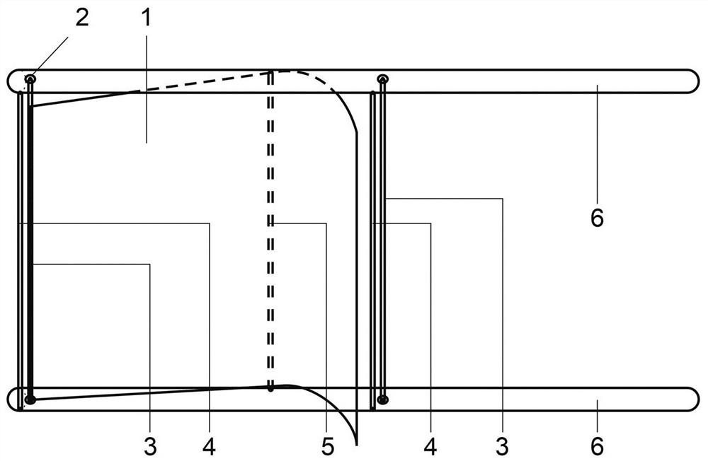
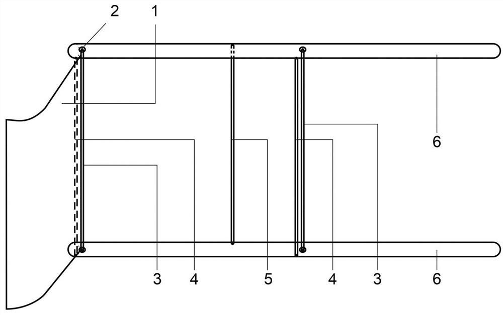
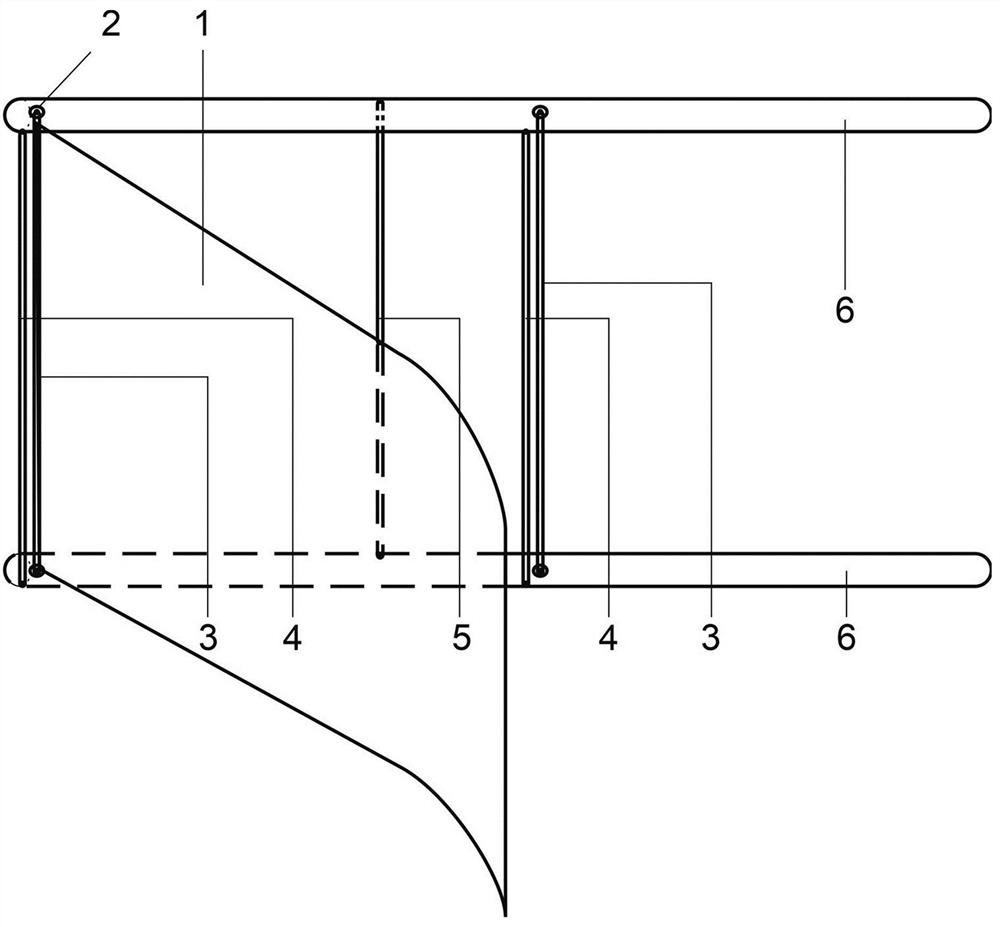
[0018] The leaf door 1 has three states under the impact of the external wind: when the external wind starts to impact the inner arc surface of the leaf door 1, the leaf door 1 is subjected to the impact force and rotates relative to the cantilever support frame until it is blocked by the outer bar. 5 Blocking no longer rotates to its leeward direction, forming the leaf door in an outwardly tilted closed state ( figure 1 ); when the leaf door 1 rotates with the cantilever support frame to the outer arc surface to face the wind, the outside wind blows the leaf door 1 open until it is blocked by the inner stop rod 4 and forms the fully open state of the leaf door 1 ( figure 2 ), so that the blade door does not form resistance to the rotation of the main shaft of the wind turbine; when the downwind and headwind are switched, the blade door 1 presents ( image 3 )state. The leaf door 1 can be opened and closed relative to the plane where the cantilever support frame 6 and the ge...

Embodiment 2

[0029] The number of blade door shafts 3 of the combined fan blades 7 is the same as that of the blade doors 1, and one blade door 1 corresponds to one blade door shaft 3. The number of blade doors 1 of the type fan blade 7 can be set as two to five, and the blade door shafts are arranged sequentially along the extension direction of the cantilever support frame to the generator main shaft 8 from the free end of the cantilever support frame (6); The vane door 1 is in the shape of an "integrated semi-arc rectangle", one end is set in a flat plate shape, and the other end is set in an arc-shaped plate shape. One end of the shape is fixed on the blade door shaft, the inner arc surface of the arc plate end is set against the wind, and the central angle of the inner arc surface of the arc plate end does not exceed 90°; the blade door 1 is impacted by the external wind Next, there are three states: when the external wind starts to impact the inner arc surface of the leaf door 1, the...


PUM


Abstract

The invention relates to a spiral blade unimpeded vertical-axis wind turbine wind wheel, and aims to achieve the purposes of high wind energy utilization rate and low production cost. The spiral blade unimpeded vertical-axis wind turbine wind wheel comprises four combined type fan blades, a hub and a turbine main shaft; each combined fan blade comprises two cantilever supporting frames, a blade door, a blade door shaft, a bearing, an inner stop lever and an outer stop lever; the two cantilever supporting frames with the same length are parallel to each other and are arranged up and down, and the cantilever supporting frames are vertically fixed with the turbine main shaft; two bearings of each blade door shaft are respectively arranged on the two cantilever supporting frames, the two bearings are oppositely arranged, the axial leads of the two bearings are overlapped, and the axial leads are parallel to the turbine main shaft; the inner stop levers are arranged on the two cantilever supporting frames on one side of the inner cambered surface of each blade door and are parallel to the blade door shafts; the outer stop levers are arranged on the two cantilever supporting frames on one side of the outer cambered surface of each blade door and are parallel to the blade door shafts; and the ends, away from the turbine main shaft, of the blade doors are in a plane plate shape, the other ends of the blade doors are in an arc plate shape, the plane plate-shaped ends are fixed to the blade door shafts, and the inner arc faces of the arc plate-shaped ends are windward.

Description

technical field [0001] The invention belongs to the technical field of aerodynamic design and structural design of wind blades, and in particular relates to a helical blade unobstructed type vertical axis wind power generator wind wheel. Background technique [0002] Wind energy is a clean and renewable energy source. Wind power generation has the advantages of no fuel, no land occupation, no pollution, and low operating costs. The industrial development prospect is very broad; the existing wind power generator components mainly include towers, Wind rotor, pitch system, gearbox, generator, converter, control system, etc.; the wind blade in the wind rotor is the main component for receiving wind energy, and it is also one of the most critical basic components in wind power generation. The wind rotor and its The scientific design, reliable quality, and superior performance of the wind blades are the decisive factors to ensure the stable and efficient operation of the unit; the...

Claims


Application Information

Patent Timeline
Patent Type & Authority Applications(China)
IPC IPC(8): F03D3/06F03D9/25
CPCF03D3/061F03D3/062F03D9/25Y02E10/74Y02P70/50
Inventor 黄家盛李荣鑫原卓然刘子芸申国平
Owner 申国平
Why Eureka
Try Eureka